Table of Contents
Scope/Description
The purpose of this article will be to outline the process we follow when swapping to a redundant power supply from a non-redundant power supply.
For the purpose of this article, we will be using an AV15, but this process will apply to any of our units.
Requirements
- 45 Drives Storinator with a Non-redundant Power supply
- 45 Drives supplied redundant power supply
- Back metal replacement for the chassis
- Screwdriver (Phillips)
- 5/16th’s wrench or socket bit
Procedure
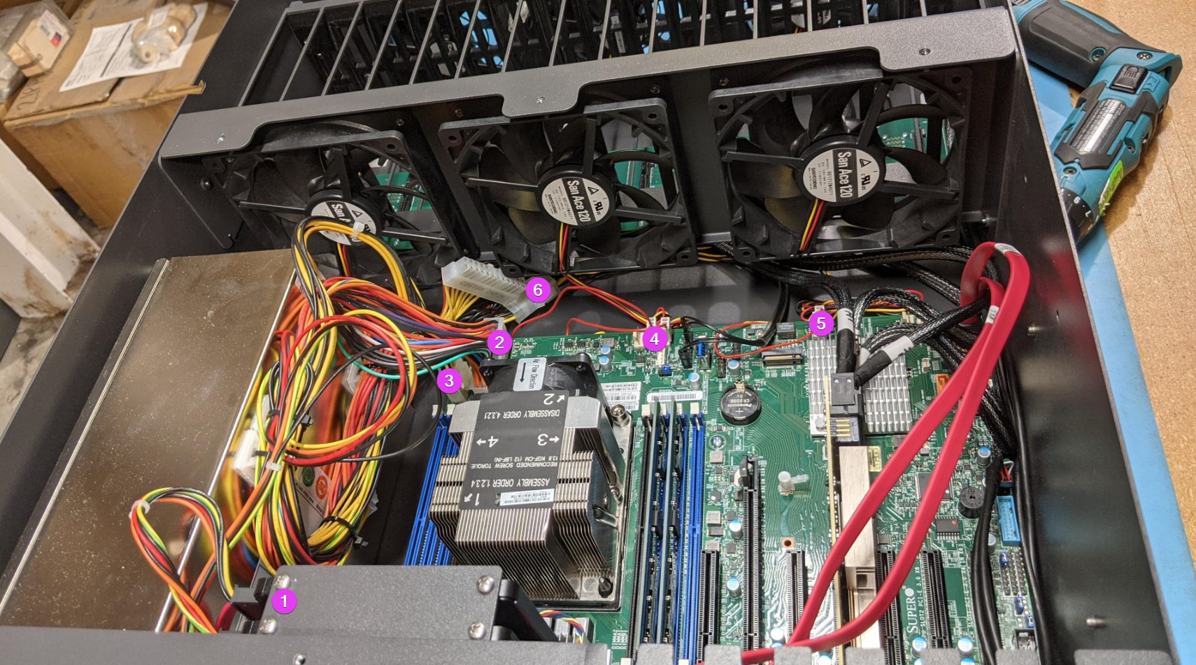
- First, we’re going to want to get a general overview of the chassis and get an understanding of our process before diving in too deep. The picture below shows our first order of business, disconnecting the headers and disconnecting the power harness.
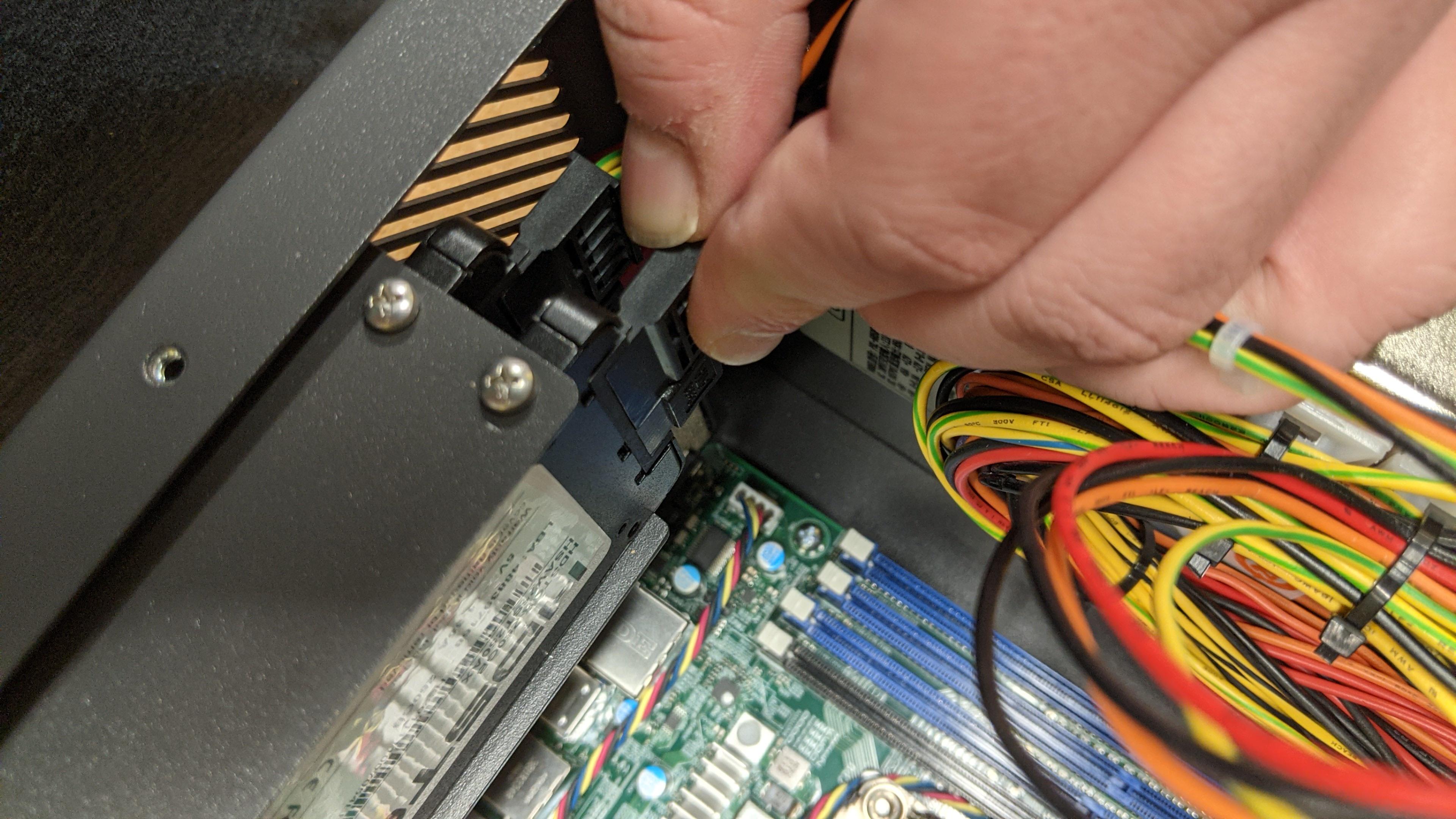
- Remove the SATA power cables from the boot bracket.
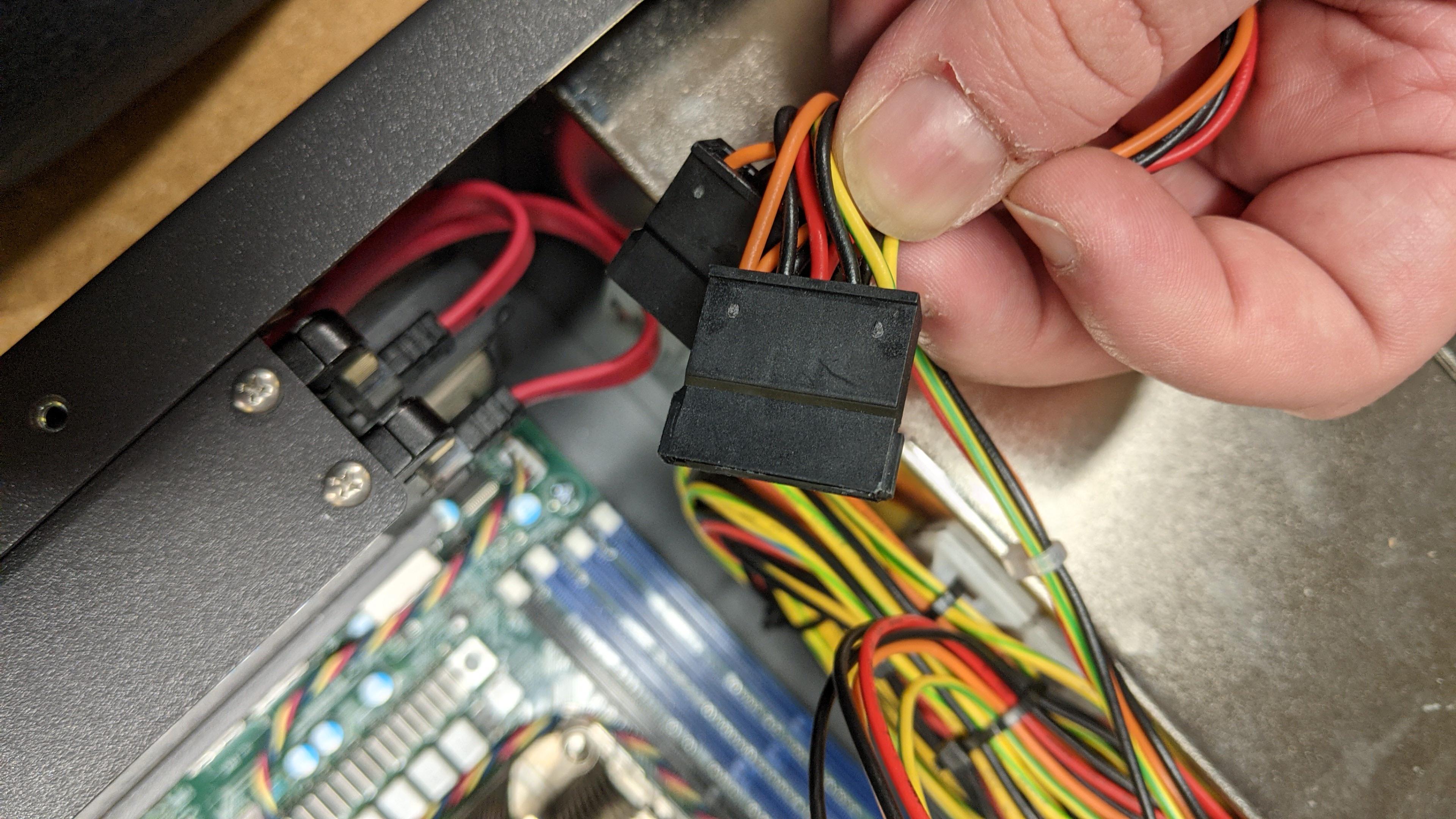
- Then, we’ll disconnect the 20 + 4 pin connectors.
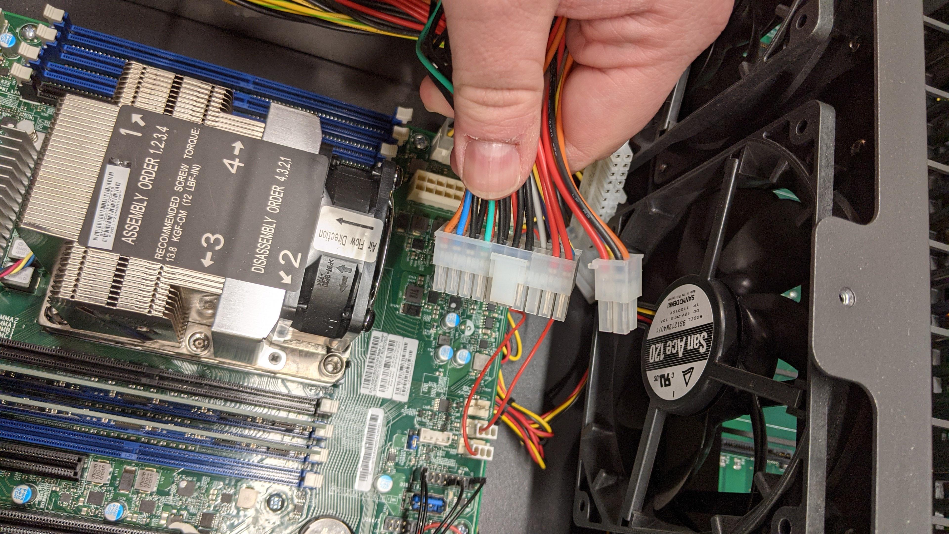
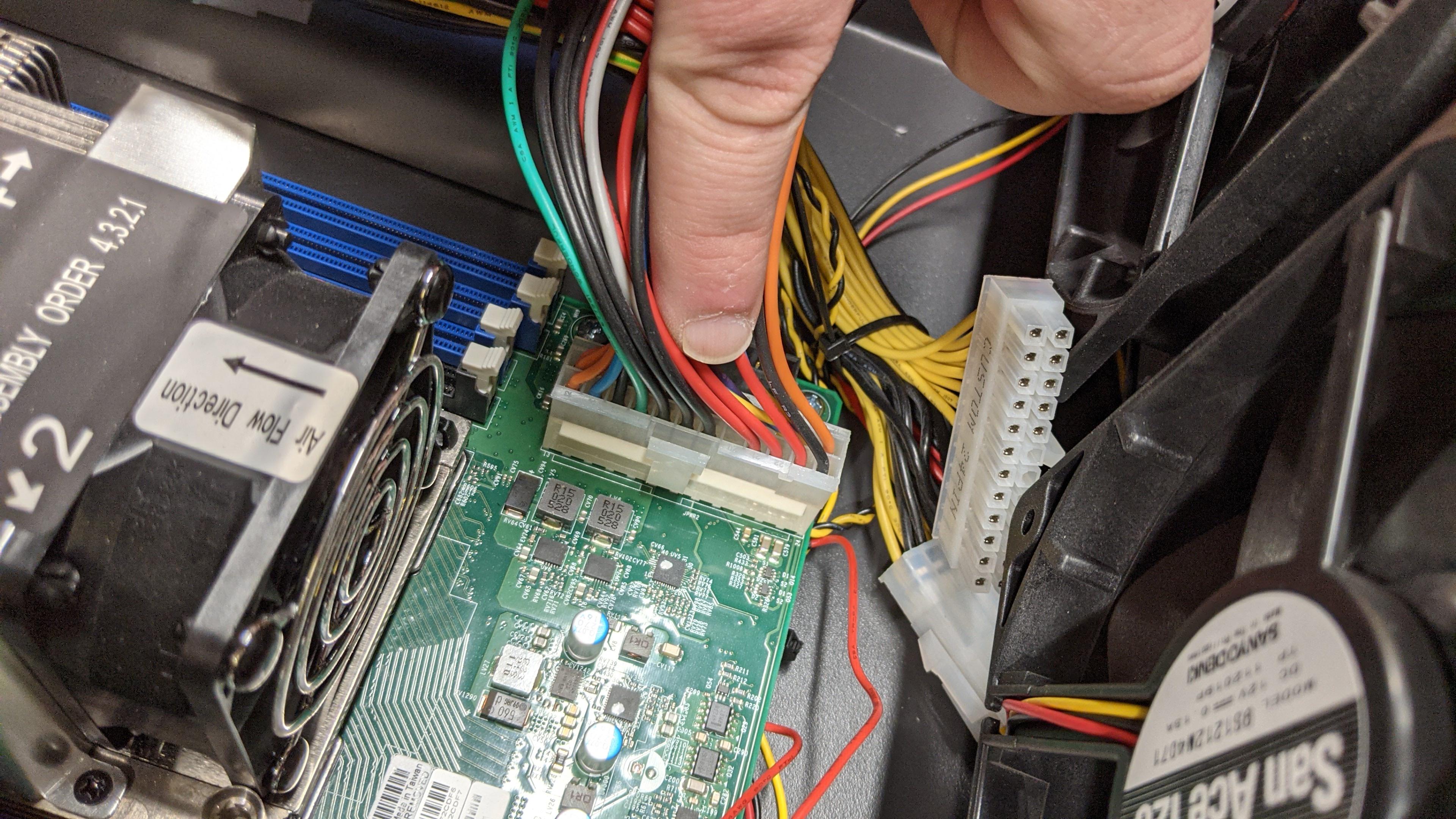
- Now we’ll disconnected the 8-pin located behind the 20+4 pin connectors.
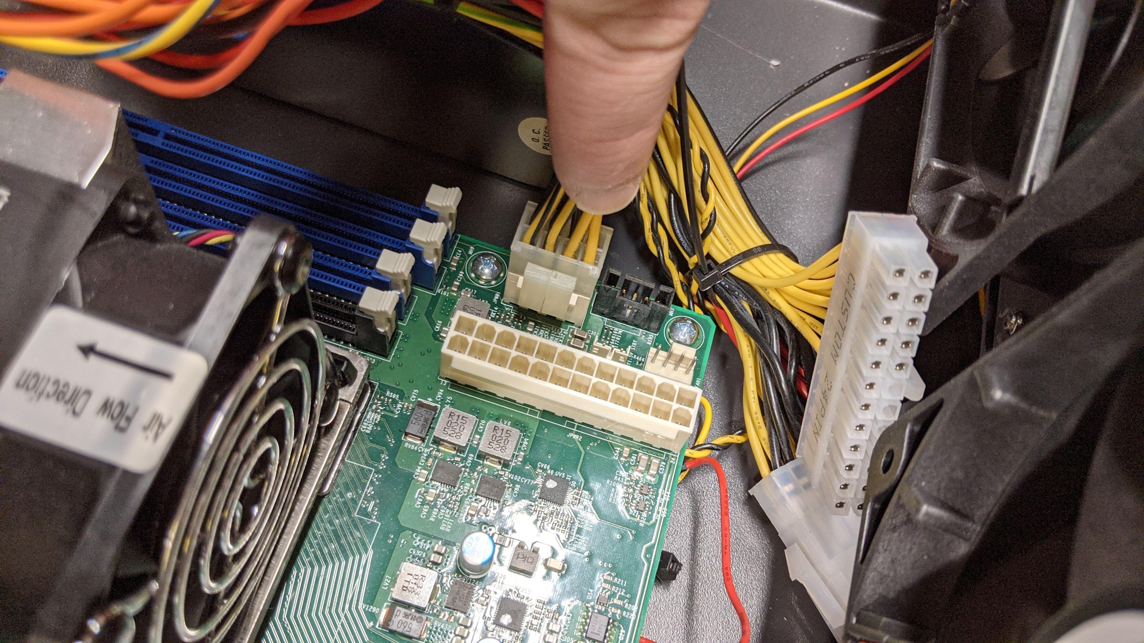
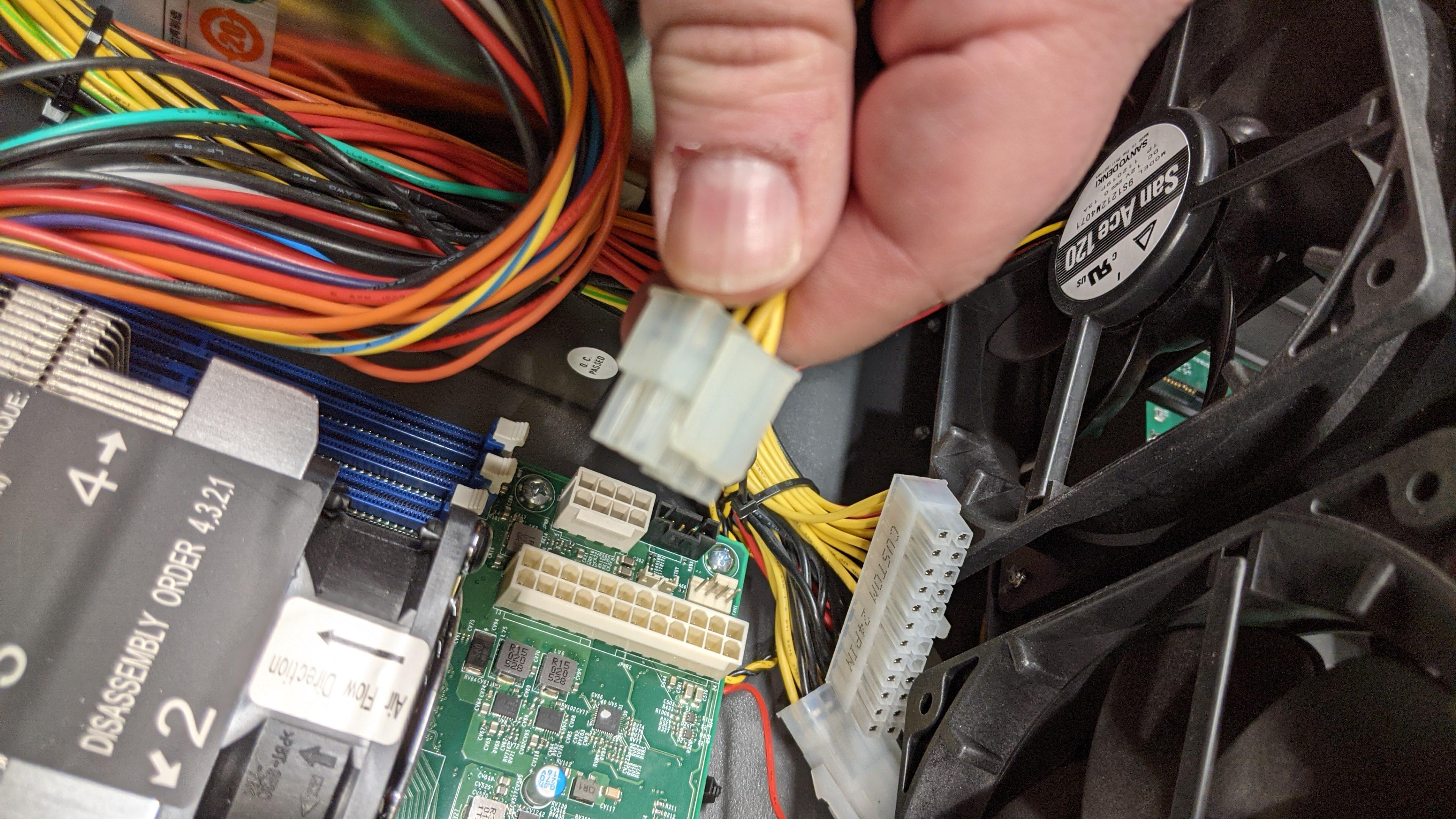
- Now we’ll remove the fan headers. These are also connected to some female connectors, they’ll need to be disconnected at the same time.
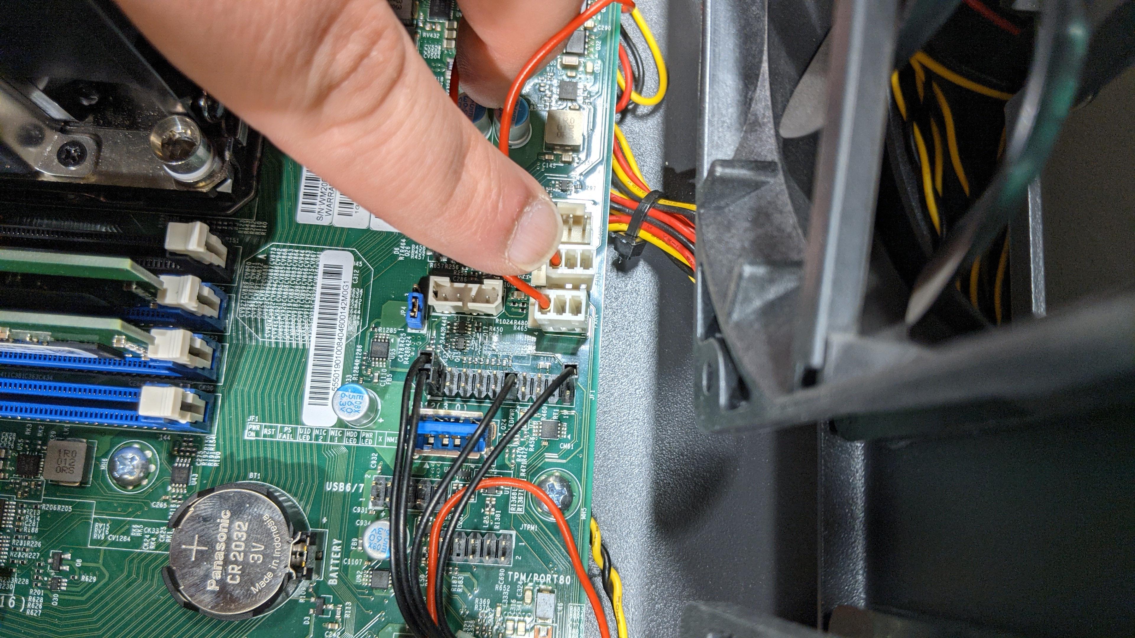
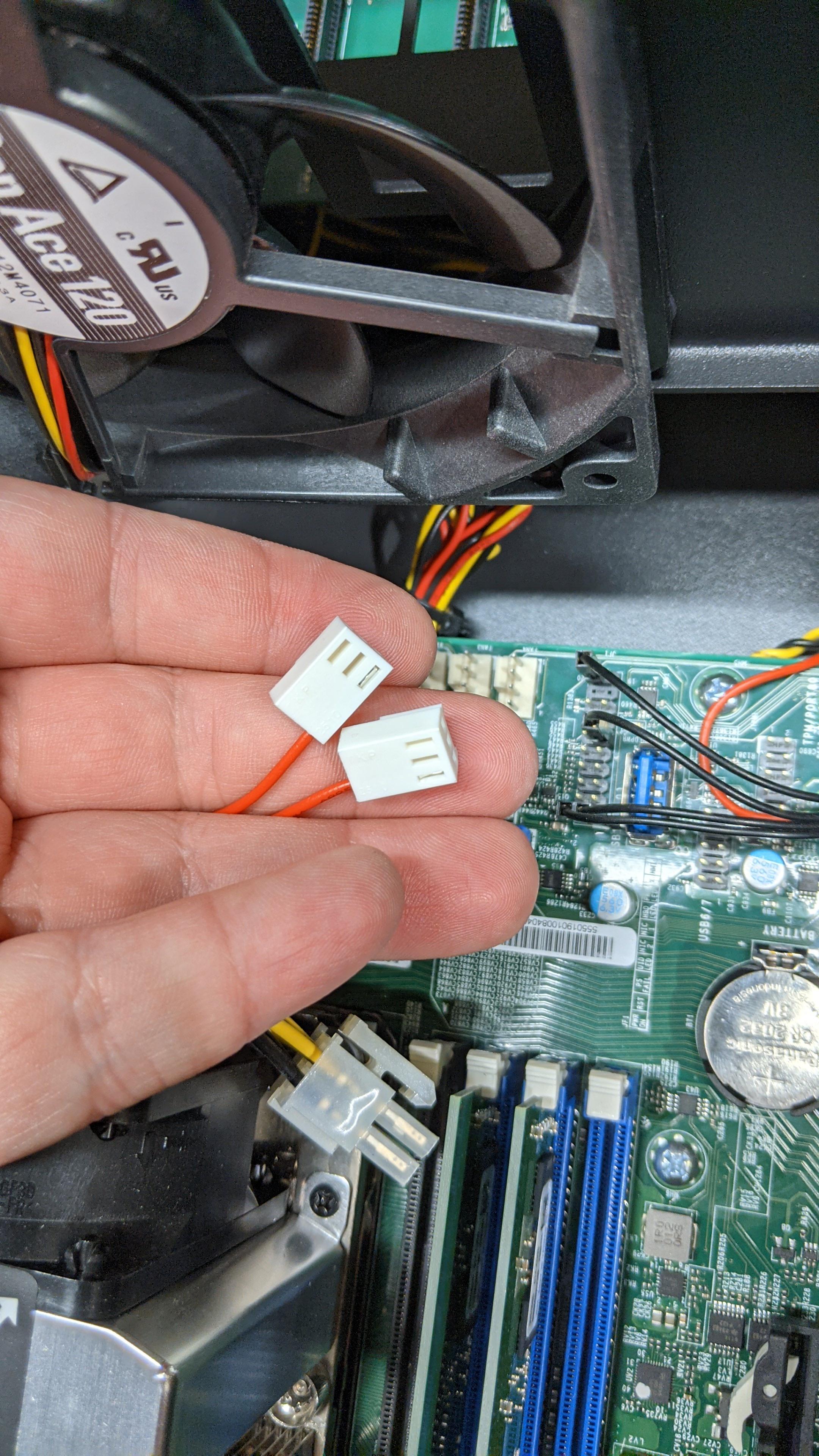
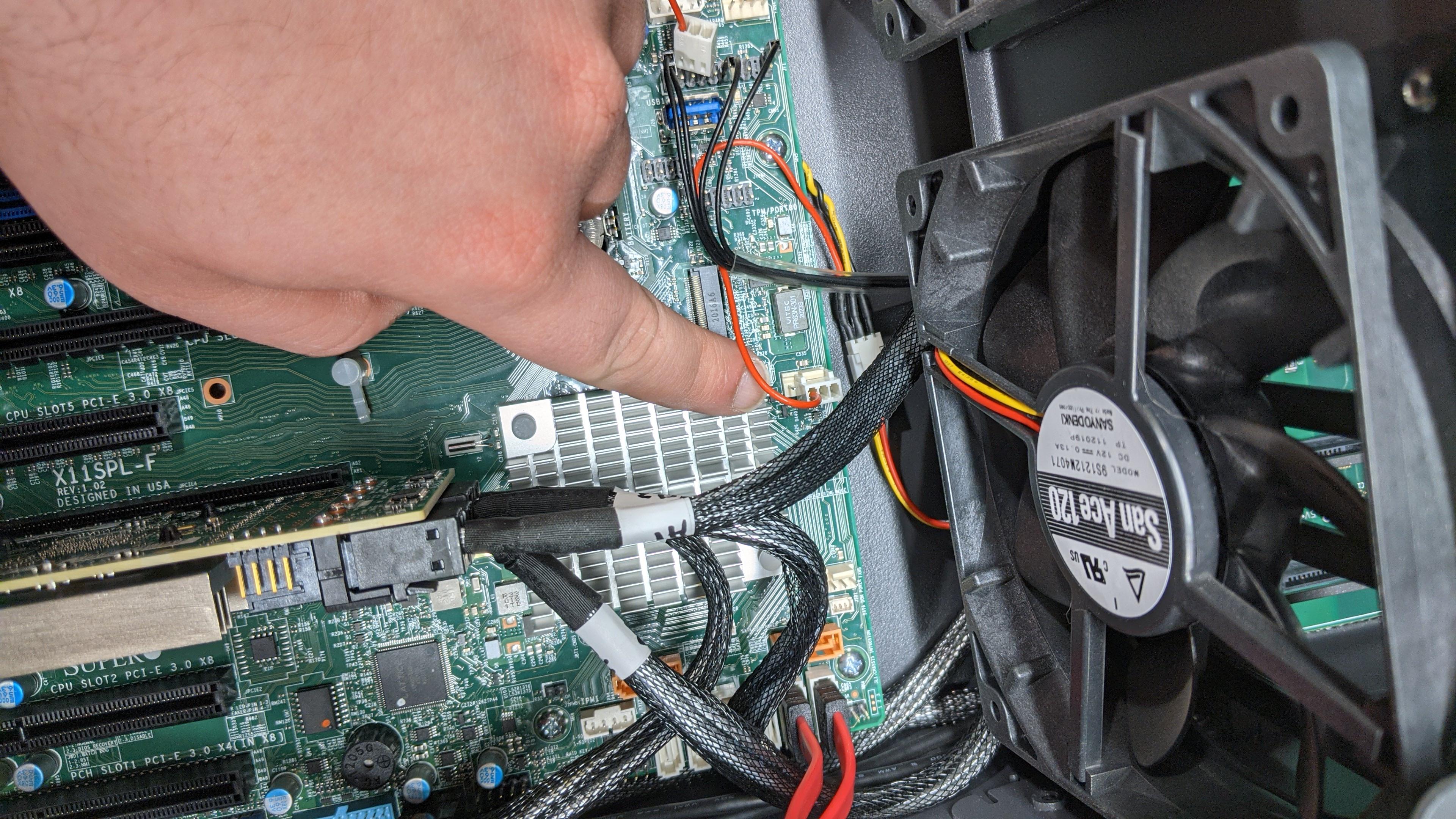
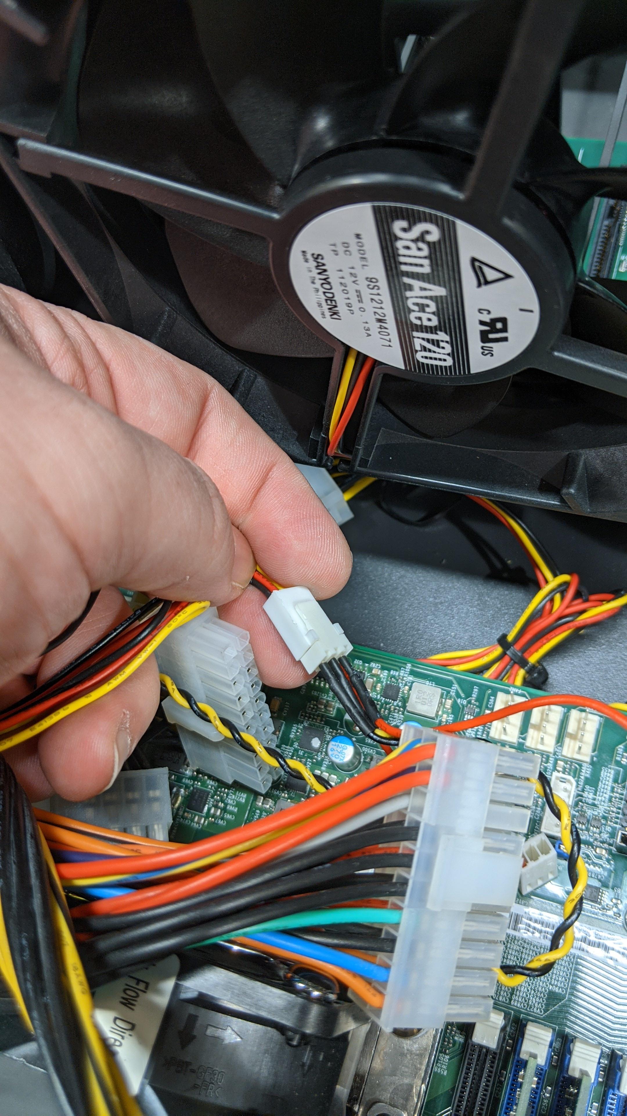
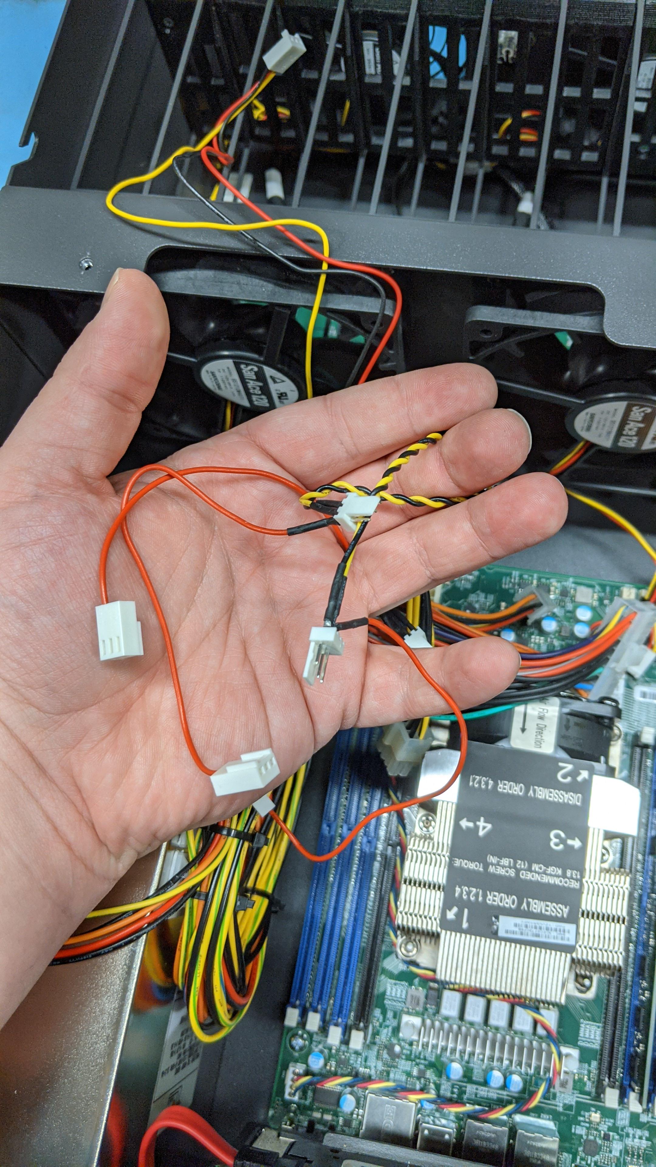
- Our next step is to unseat the power harness. This is often tucked under the fans, and in some cases you may need to remove the screws from the fan bracket to be able to access it properly.
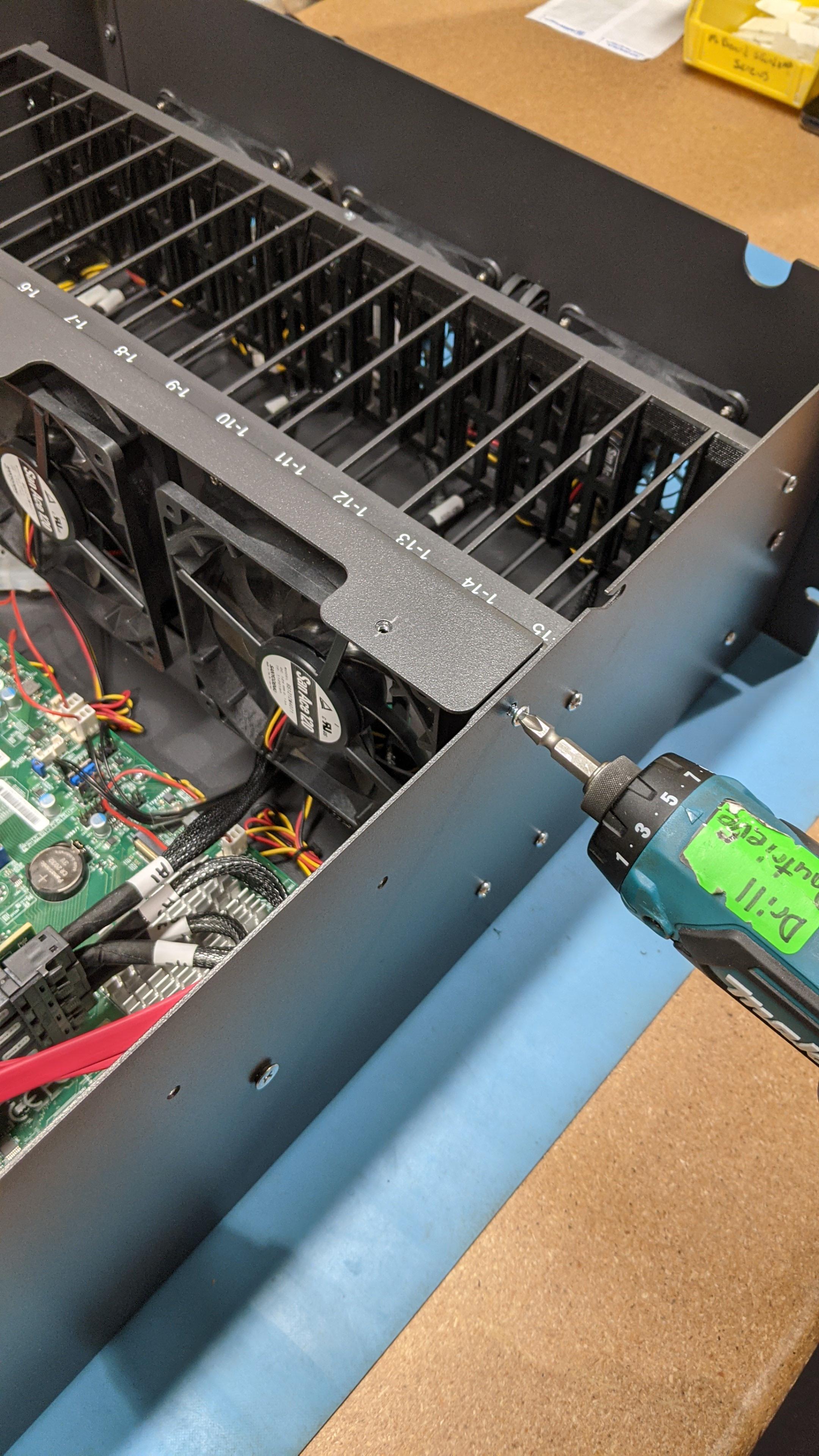
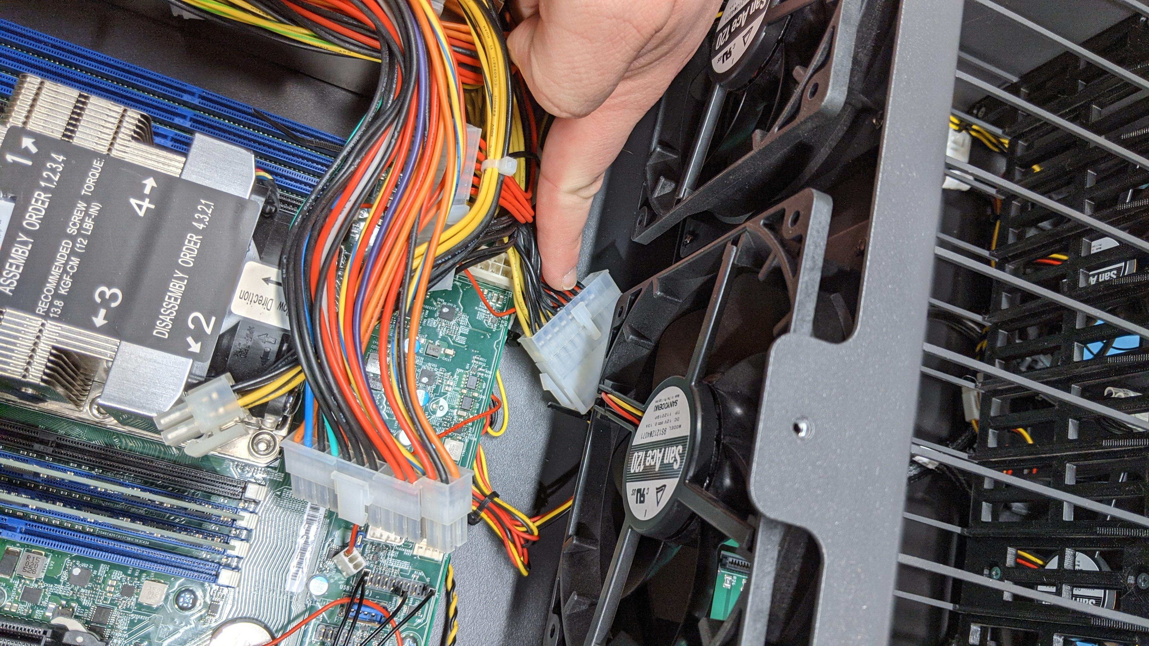
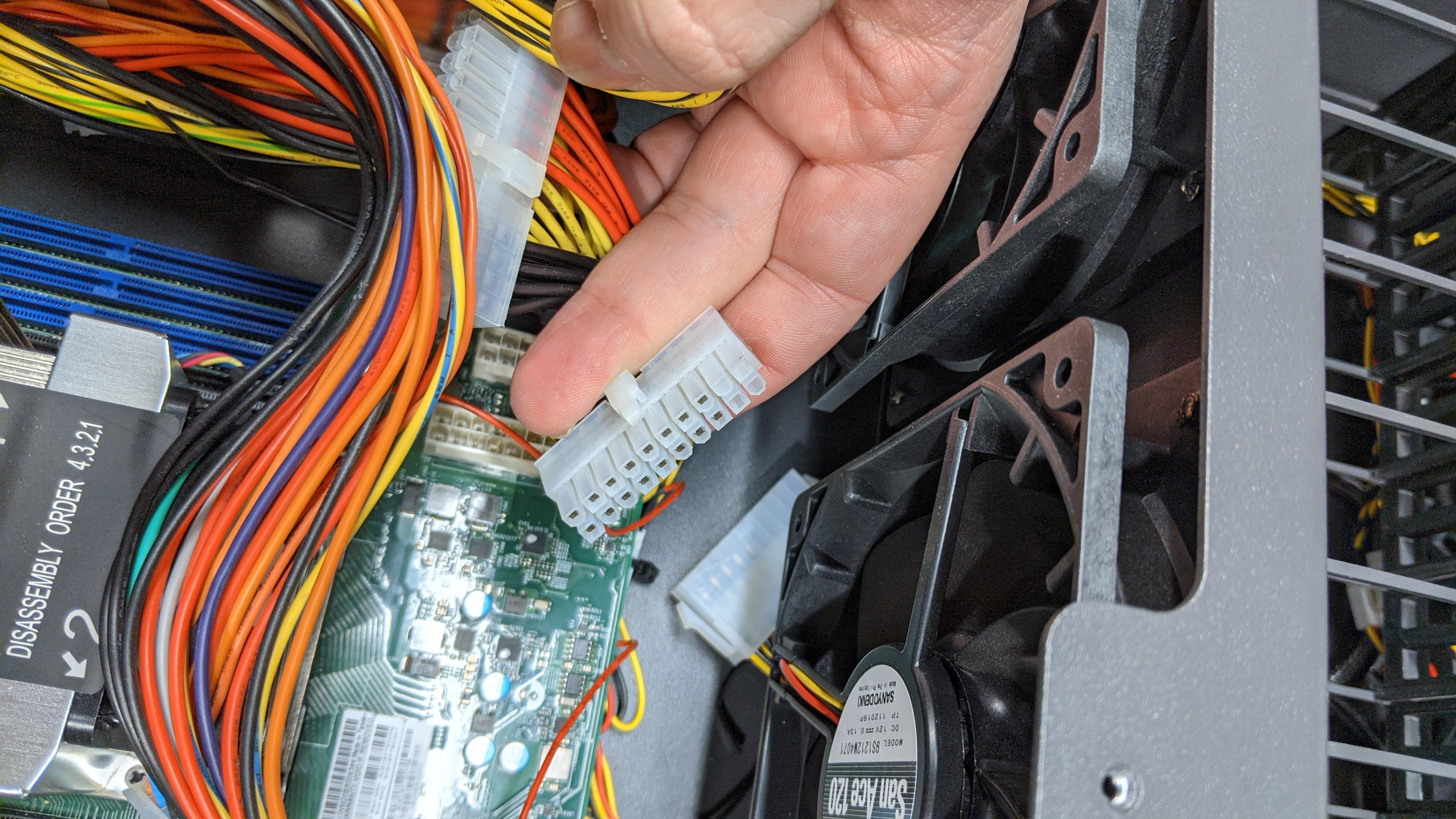
The fan bracket should already be disconnected and have the screws removed, now is the time to remove it from the chassis.

- Now that we’ve removed the fan bracket from the chassis, we can start removing the power supply by removing the screws that keep it in place. There are two mounting screws on the inside of the chassis as well.


- We can now move on to replacing the back metal plate of the unit, first step, remove the boot drive bracket.


- We’ll need to remove the screw that is holding the HBA card in place as well.


- We can now safely unscrew the back metal of the unit and remove the lug nuts that are holding it in place.


- It may be necessary to remove the screws that are holding the motherboard in place to safely install the I/O shield and the new back metal. There should be 9 screws that are used to mount the motherboard to the chassis.
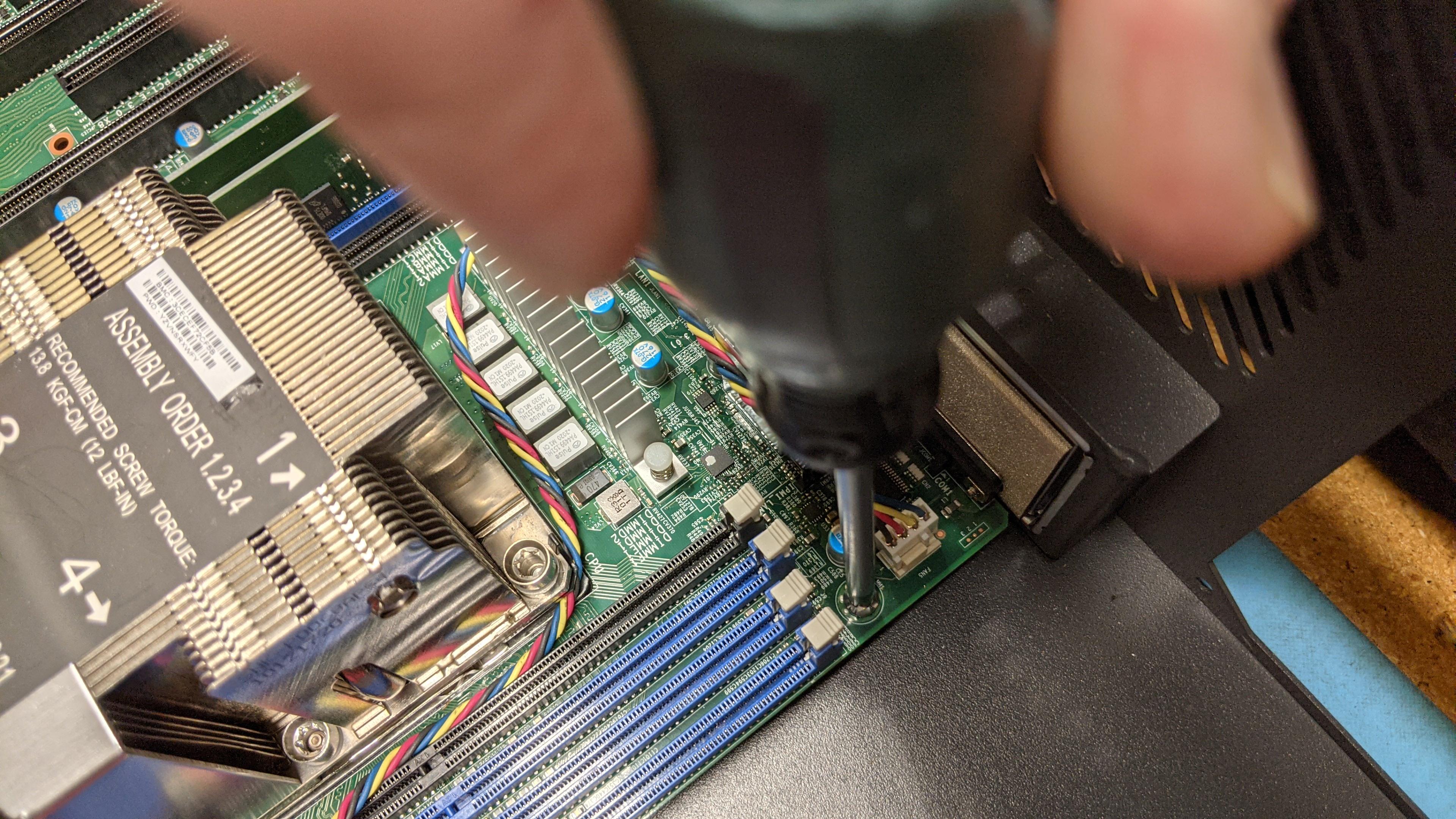
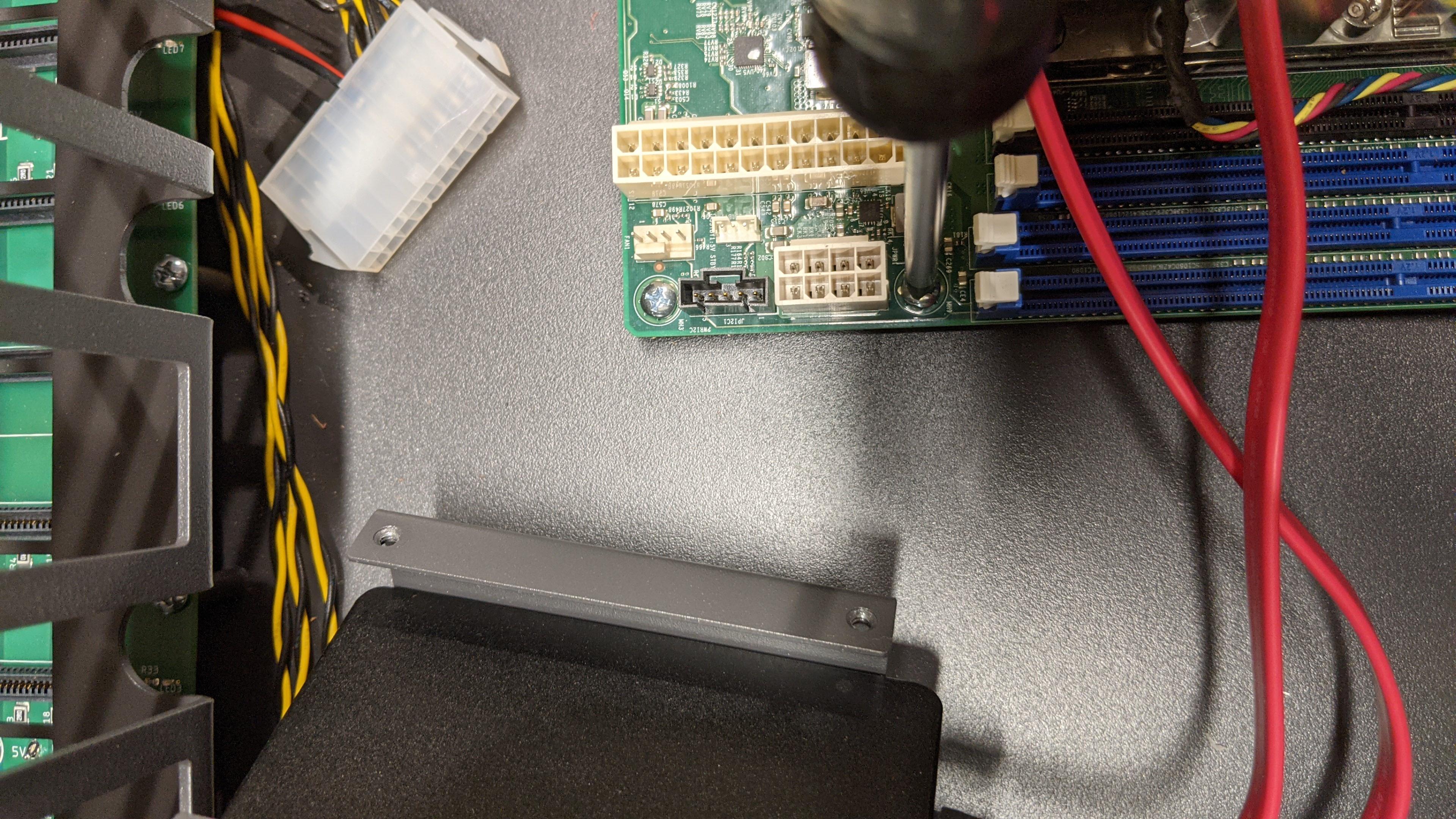
- It should now be safe to remove the back metal from the system
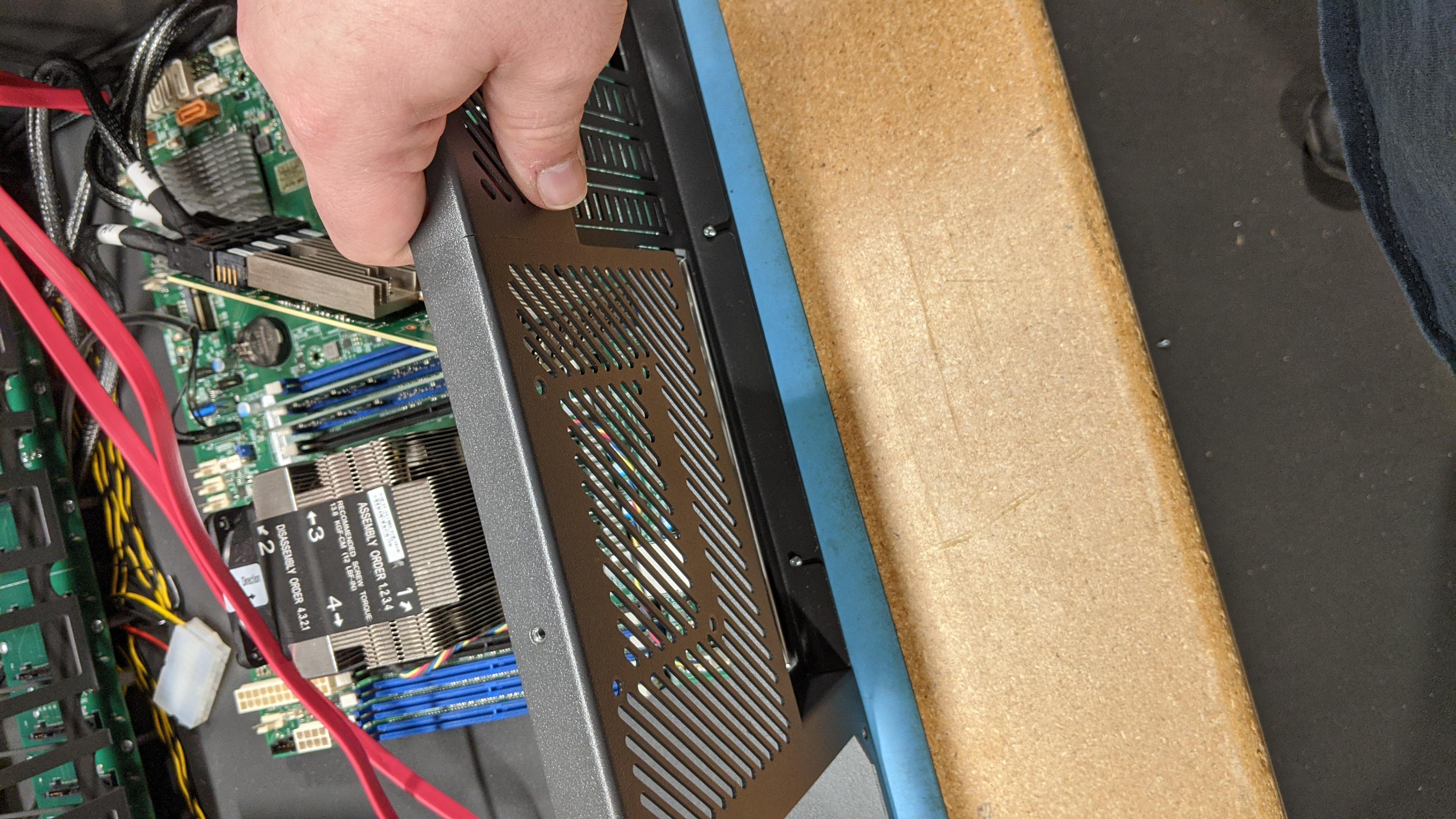
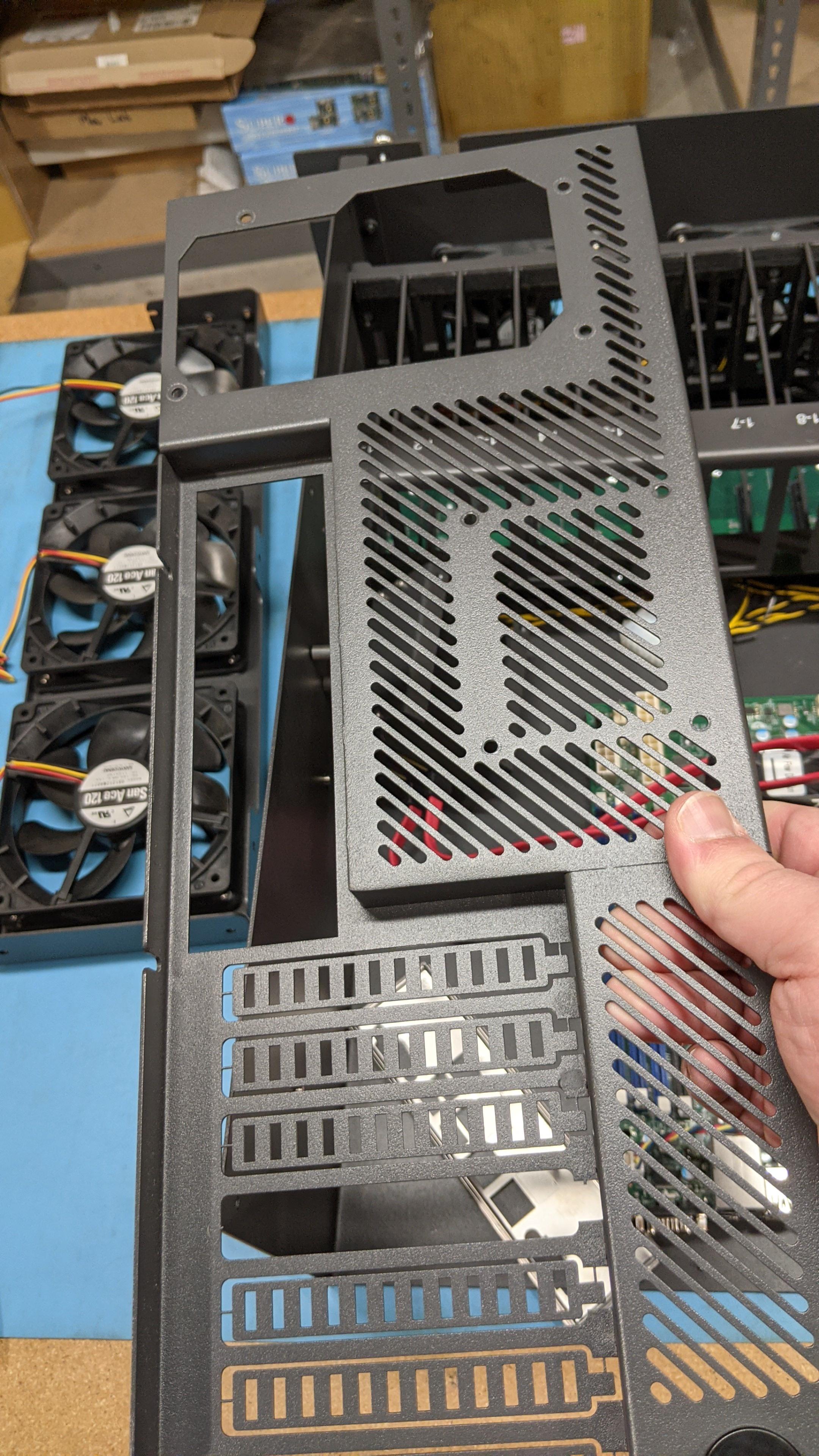
- Now the new back metal can be installed, be sure the lug nuts are as flush as can be to ensure the motherboard, I/O shield and HBA cards are able to properly fit in the chassis.
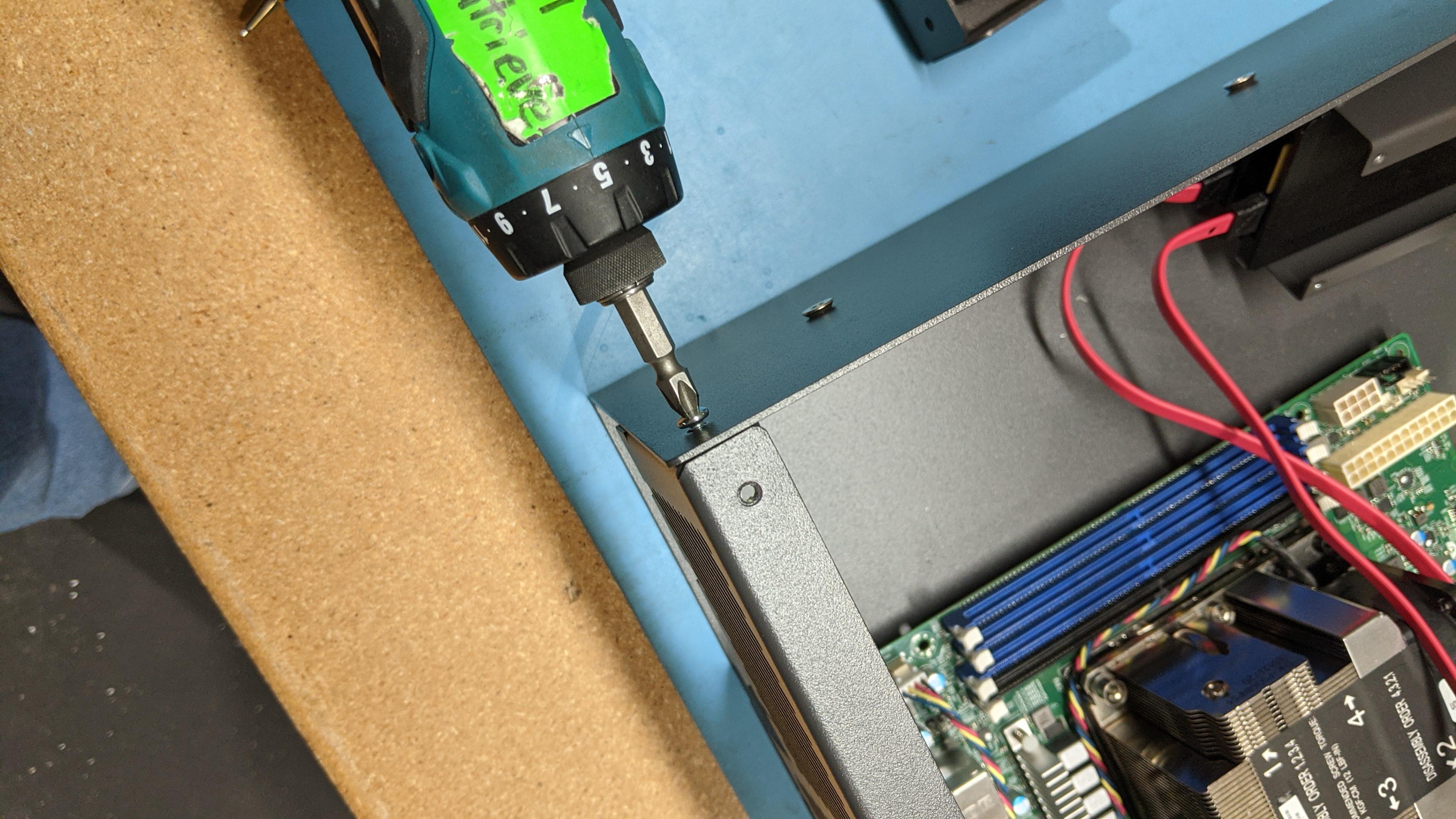
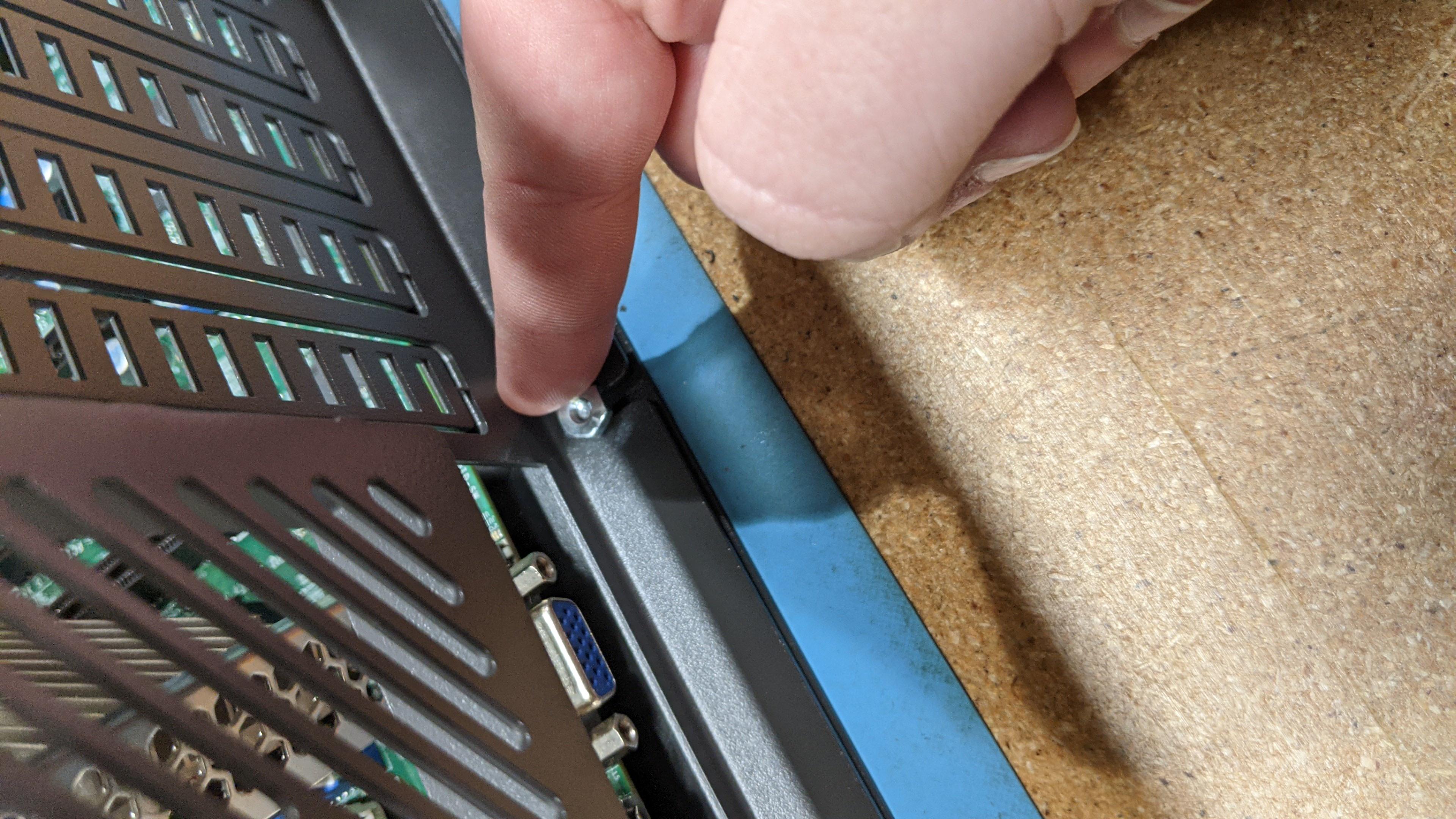
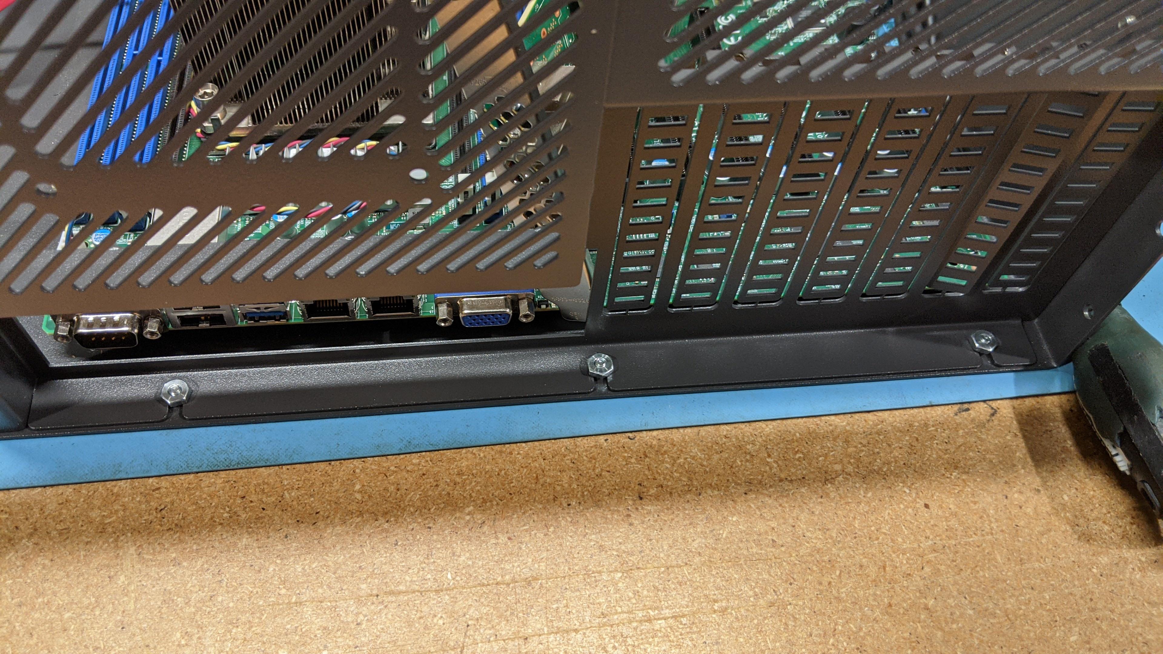
- The I/O shield can now be installed, followed by putting the motherboard back in place. The motherboard can be remounted as well.
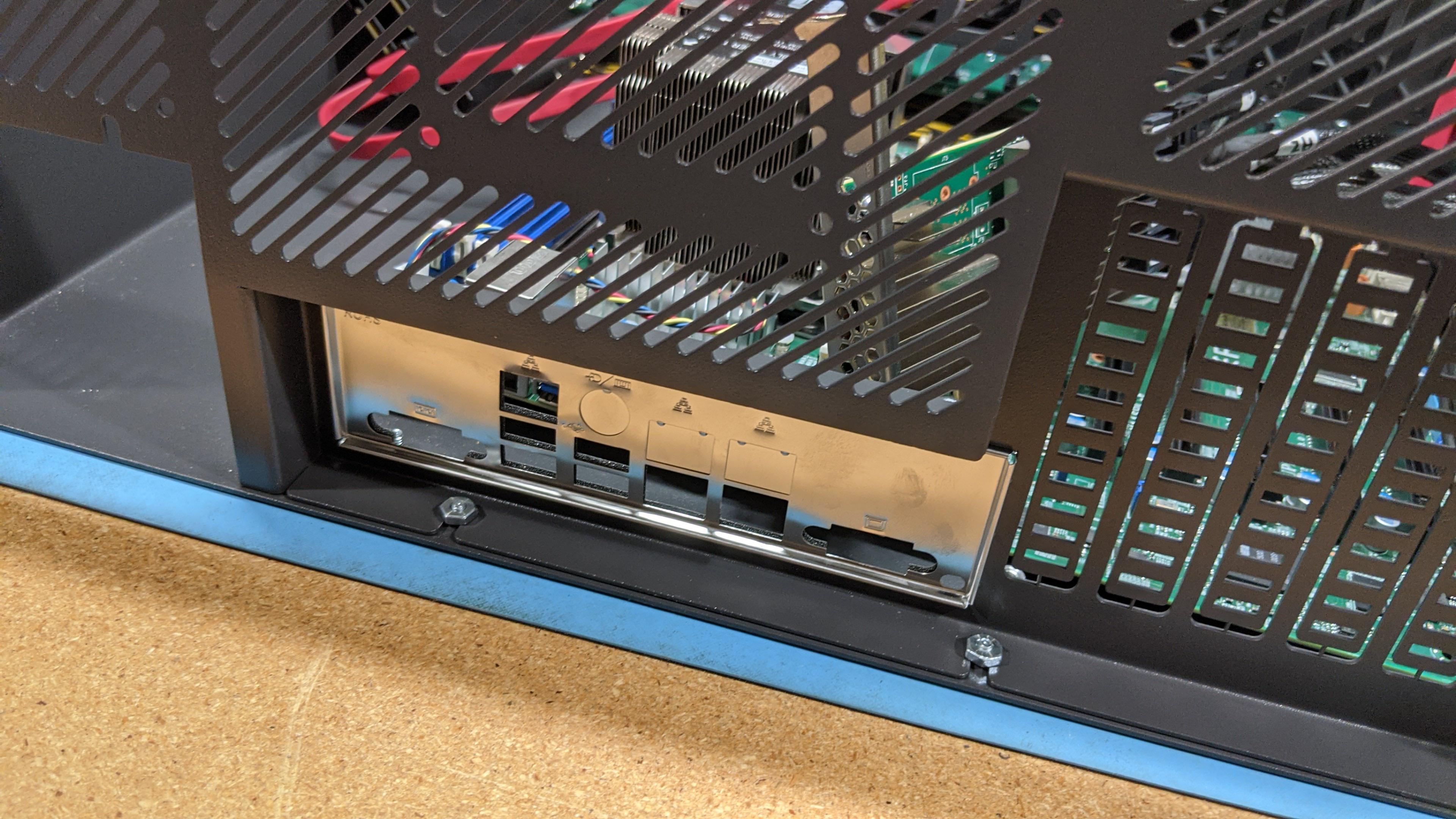
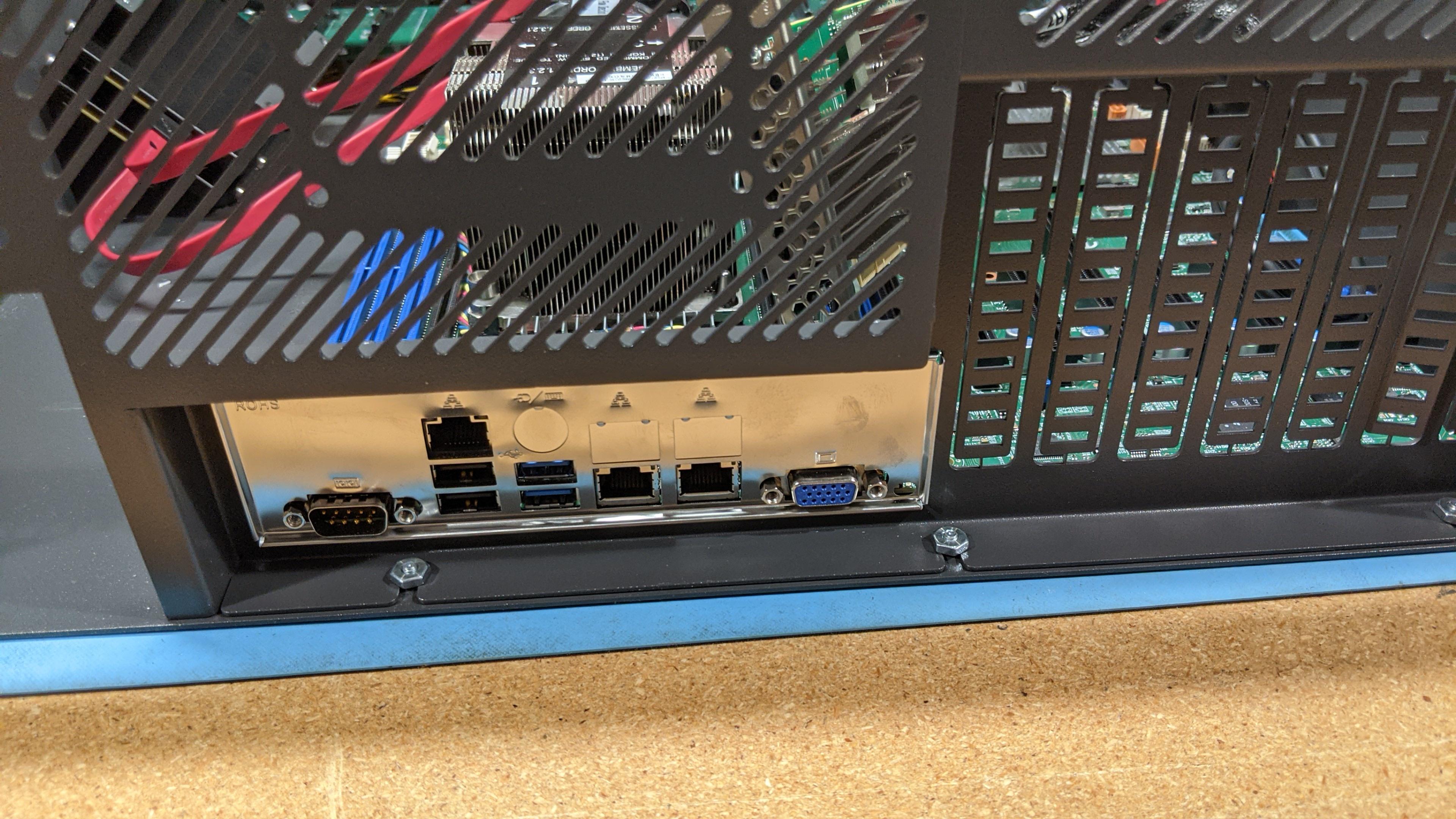
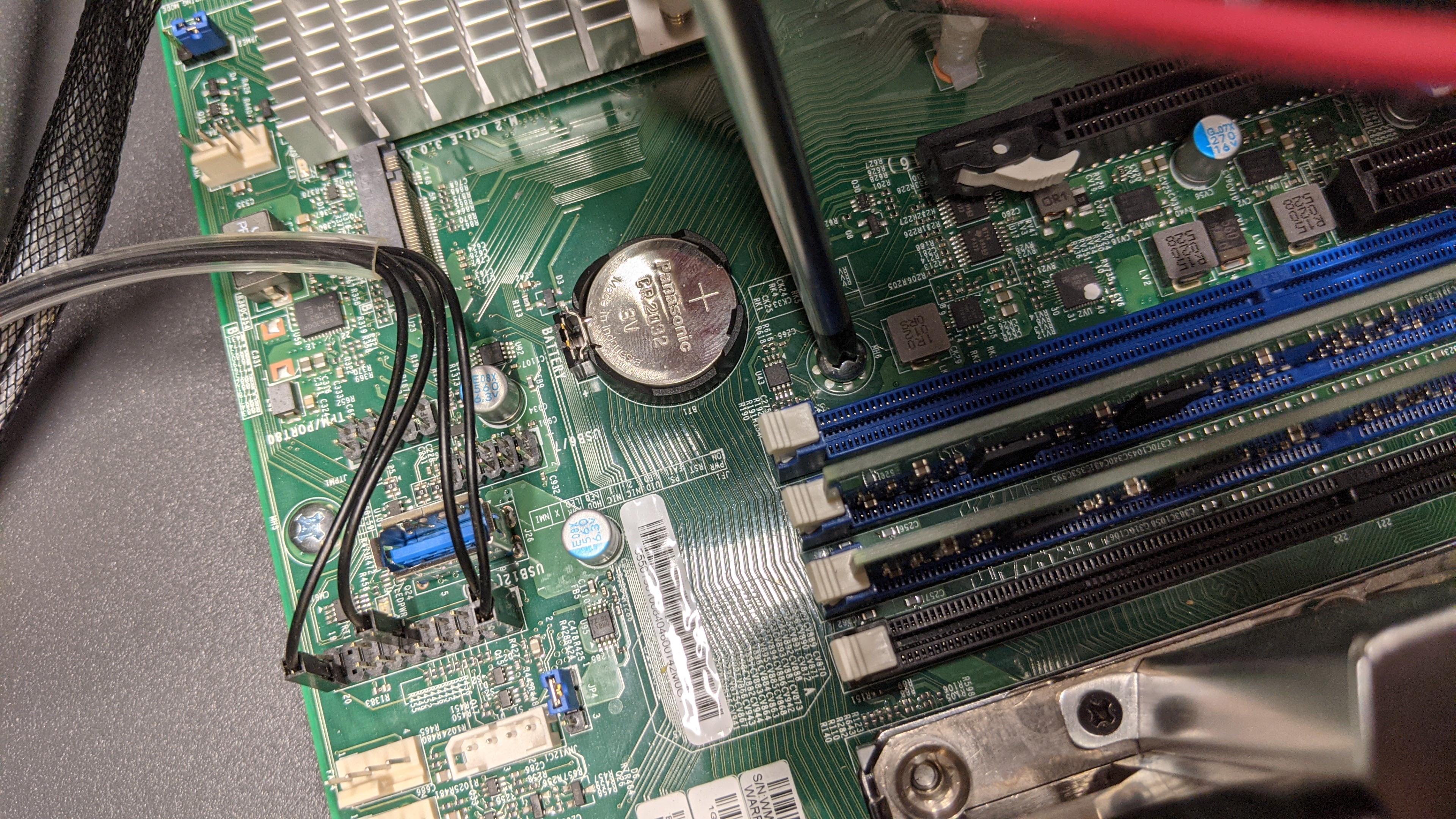
- The SSD boot bracket can be remounted to the chassis as well
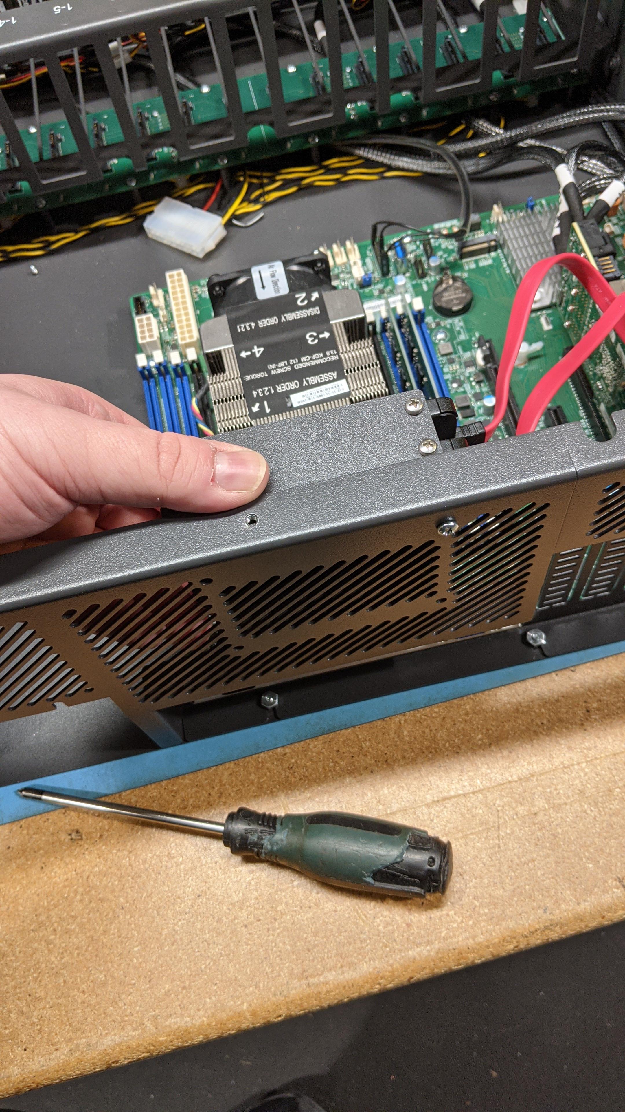
- After all these steps, we can start installing the power supply. Start by removing the power supply modules from the casing.
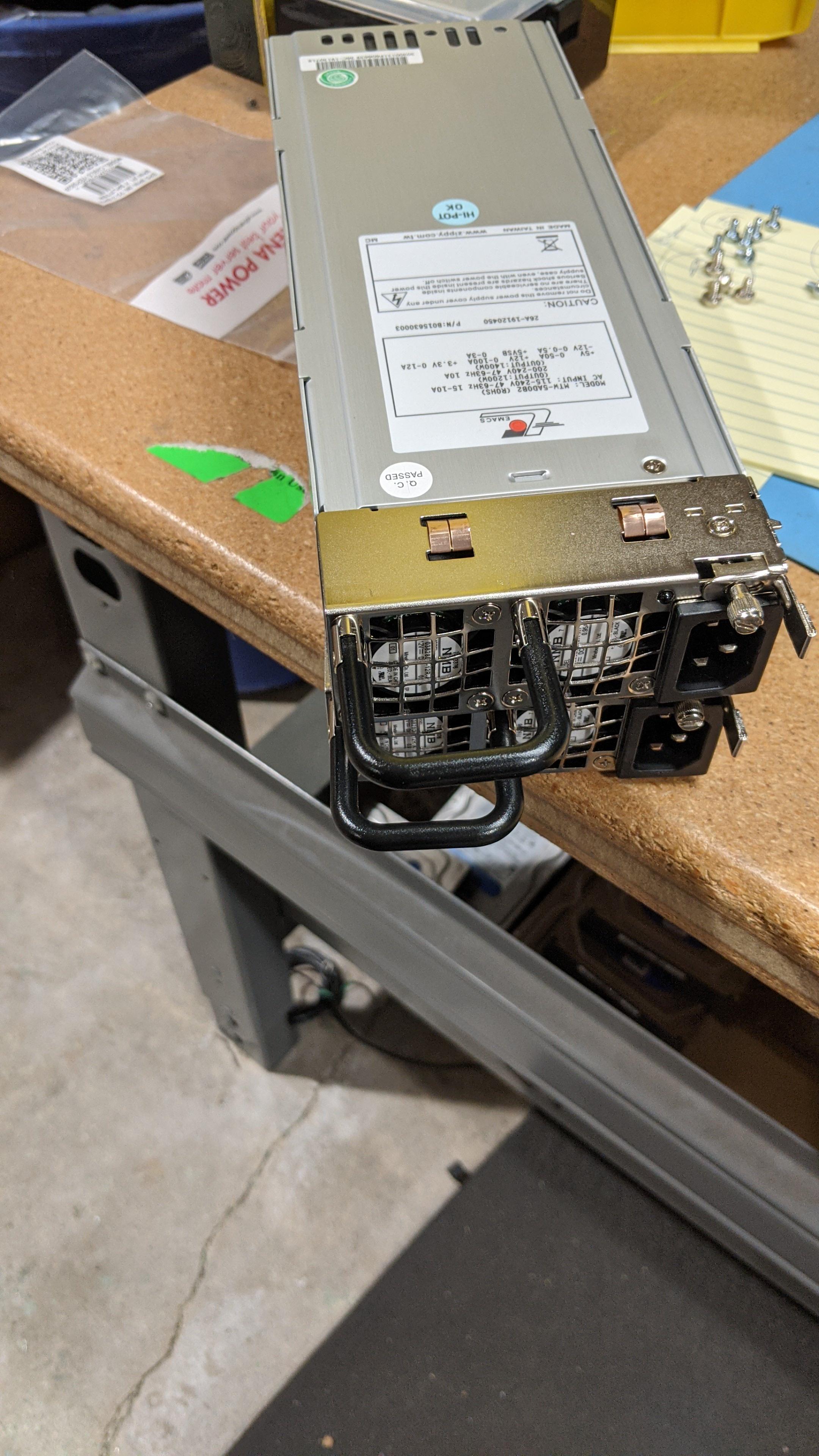
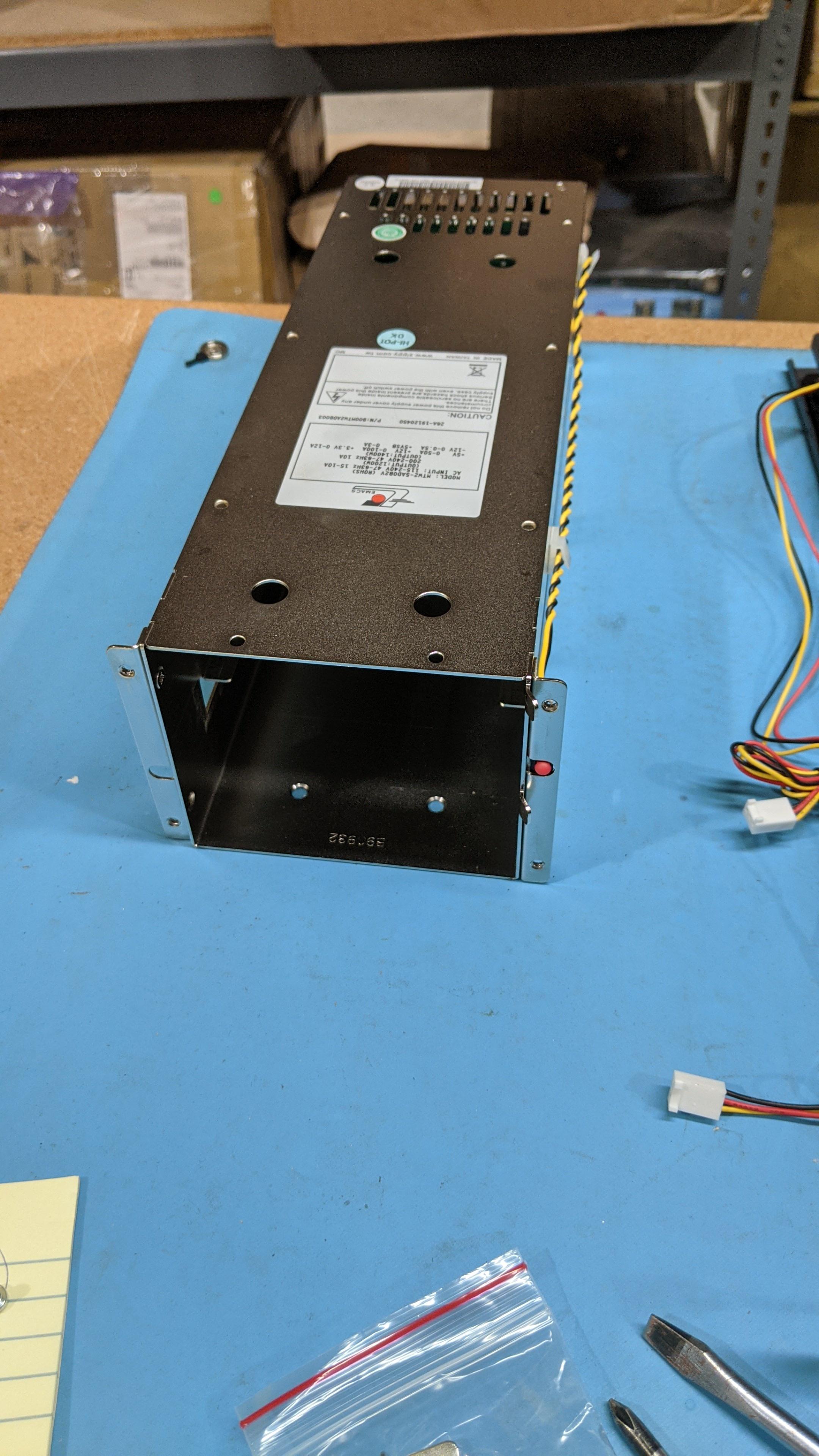
- To make this fit in the machine we’ll need to swap where the braces are installed on the casing as well. In the previous picture, we can see they’re installed on the side of the power supply. We’ll need to remove the one on the left side and place the right hand side brace with the button on the top.
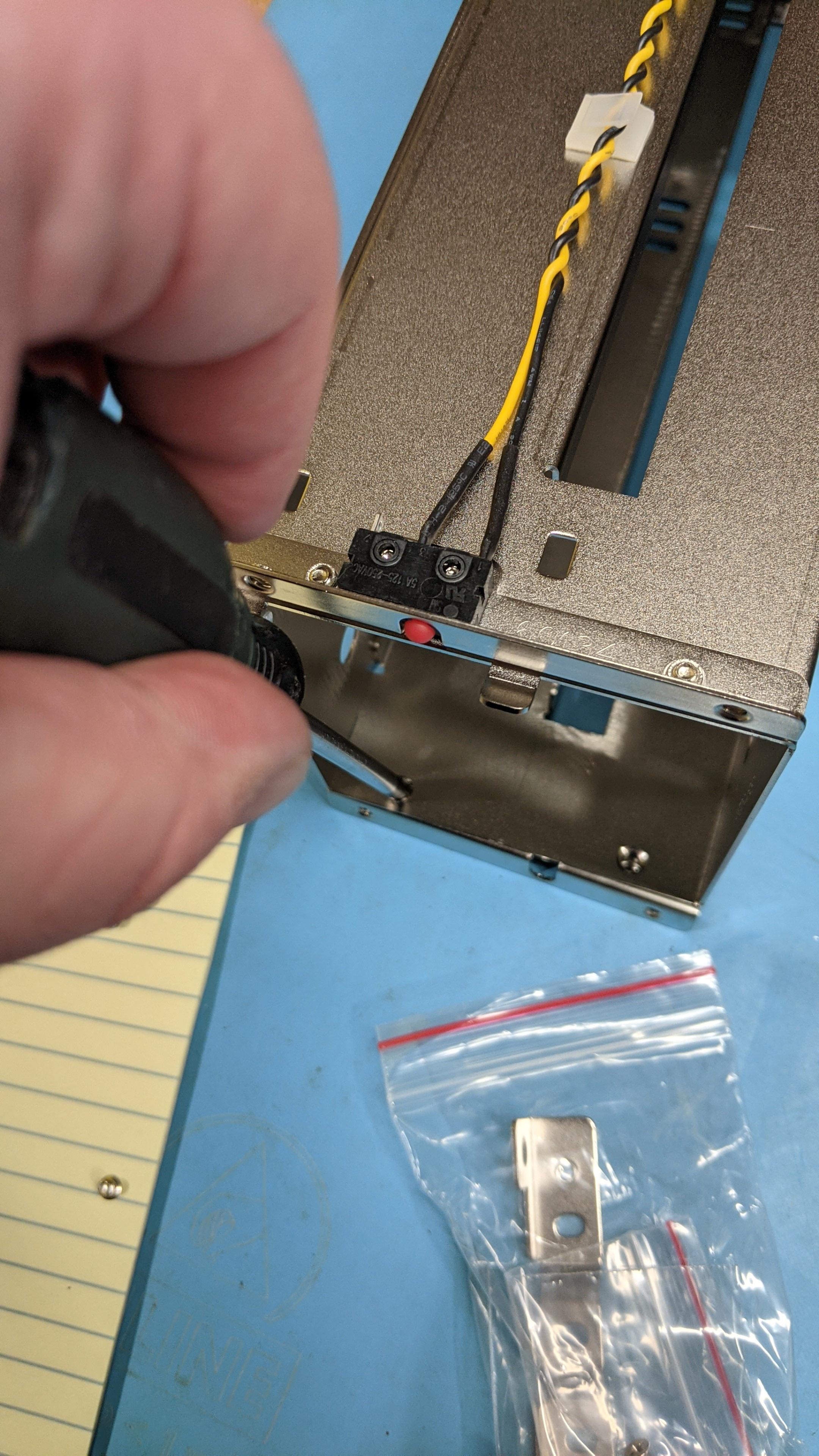
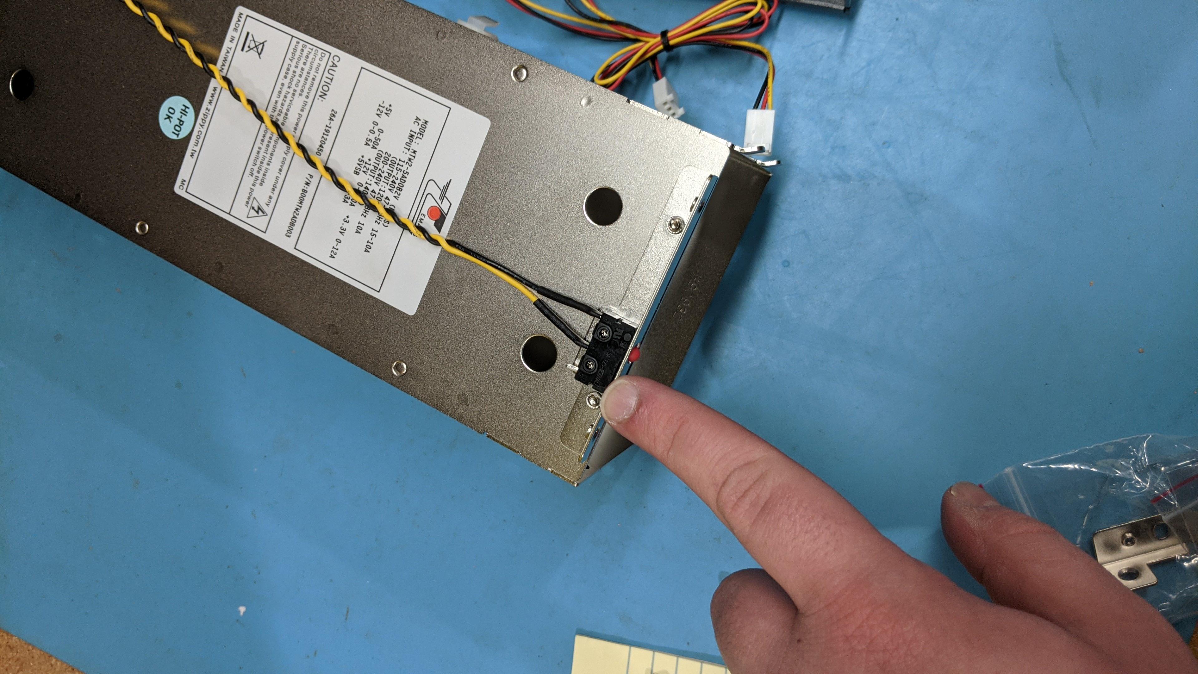
- The side of the power supply casing with the metal ‘lips’ will be facing towards the inside of the unit when it’s installed– this may take some slight maneuvering to get installed properly.
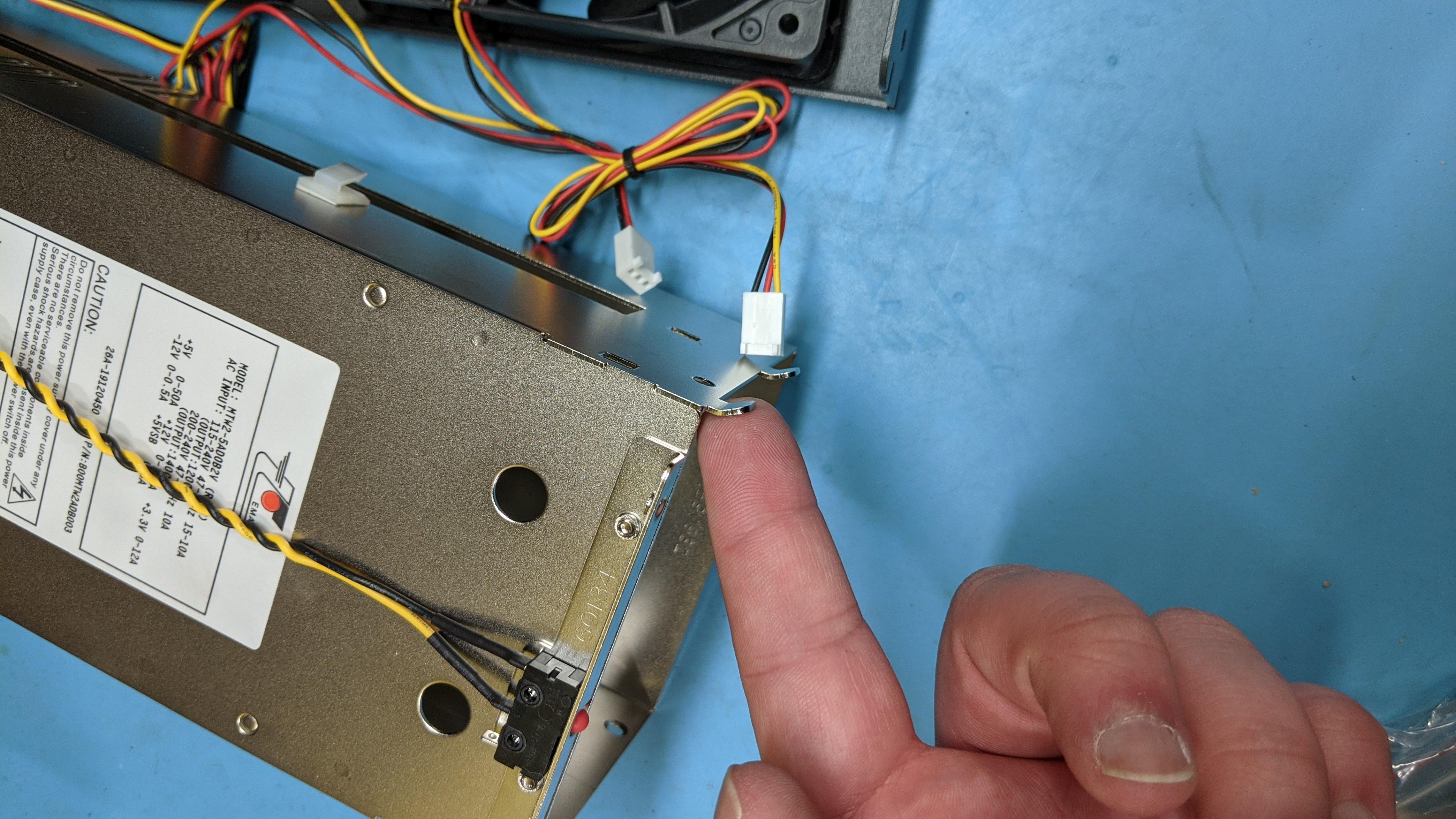
- From here, a second brace will have been included with the power supply and should in the box, we’ll need to install it on the front of the power supply so we can use it to mount the new supply firmly in the chassis.
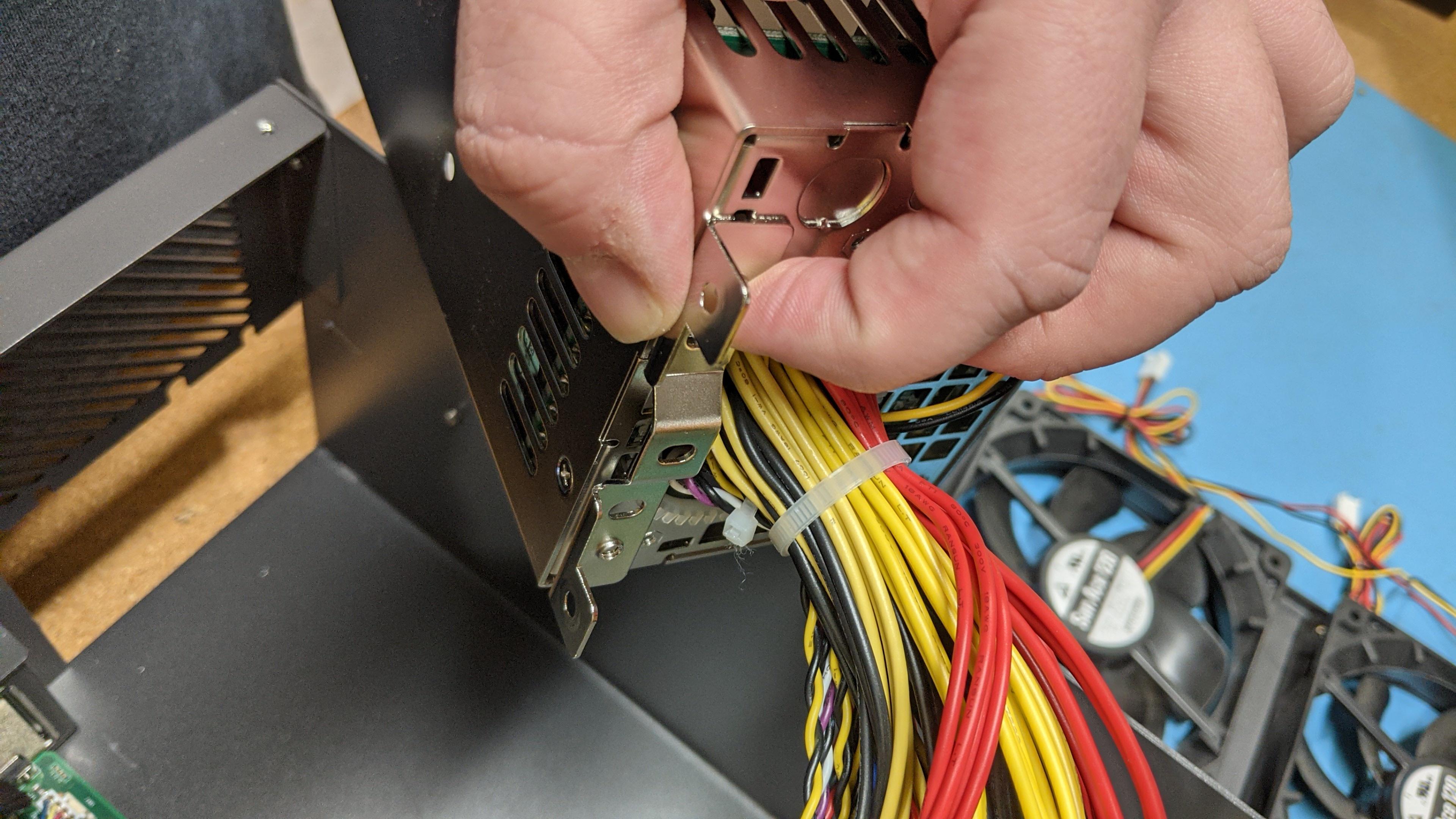
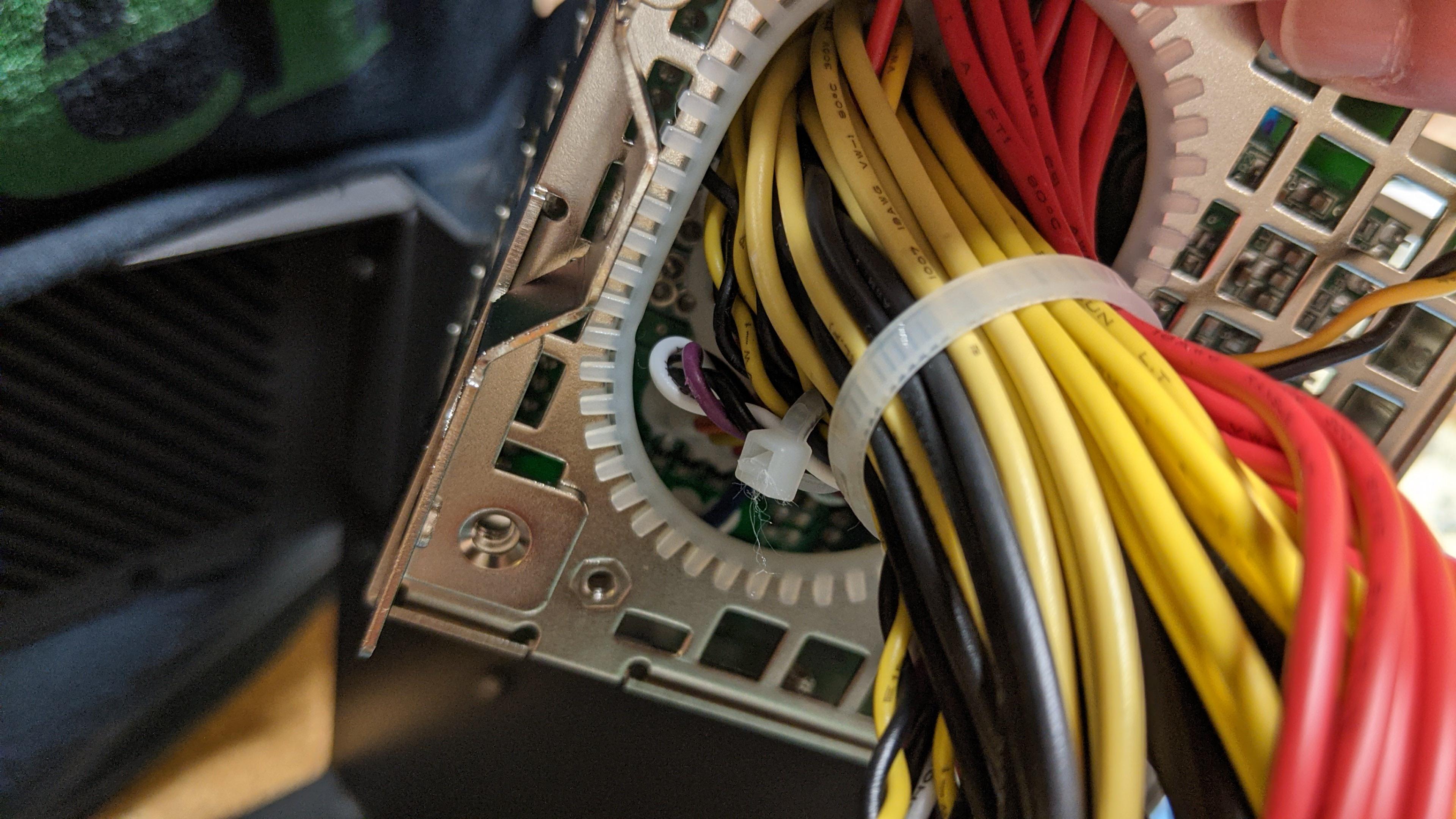
- To install this properly, you may need to remove the HDD bracket from the chassis.
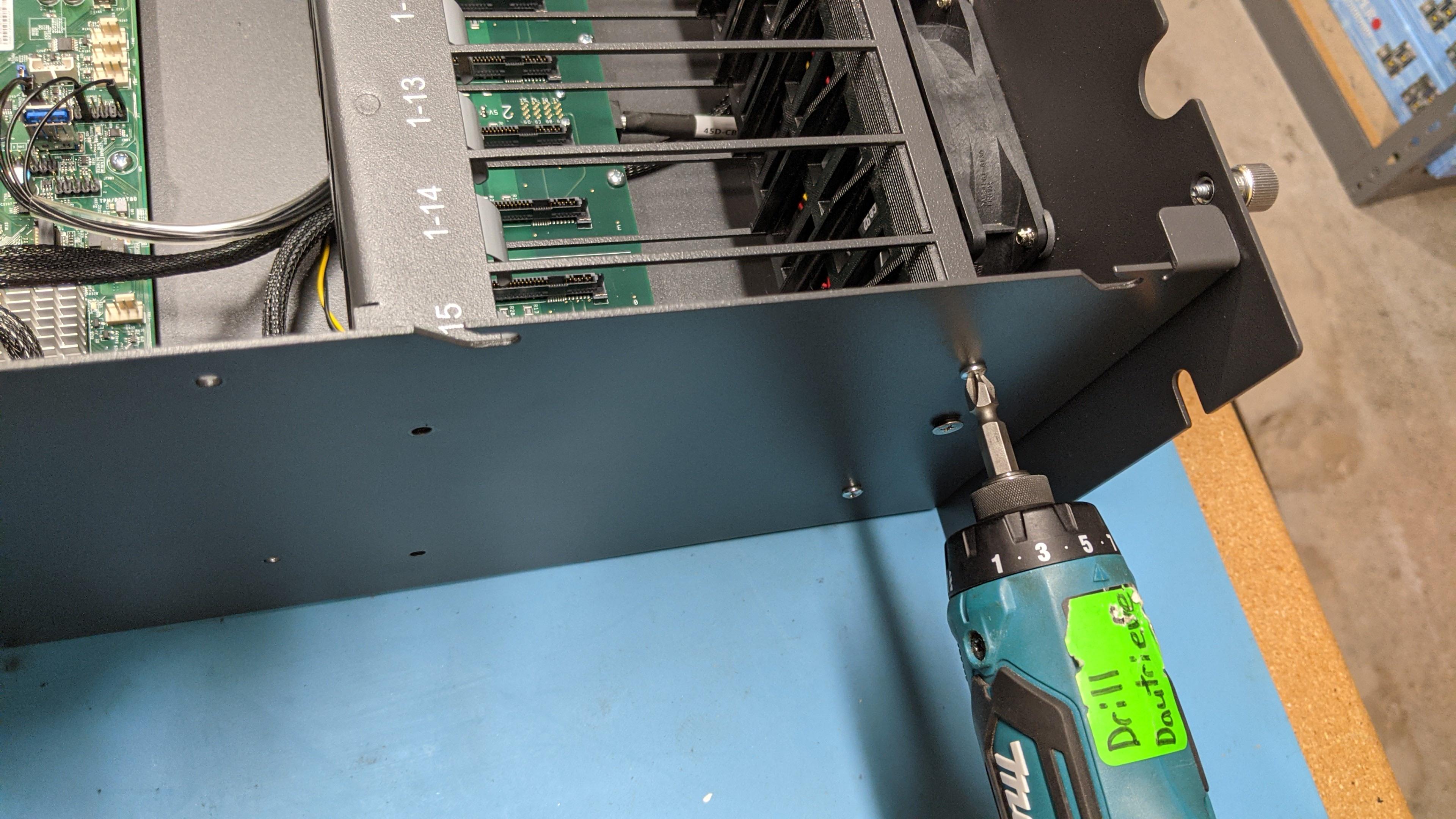
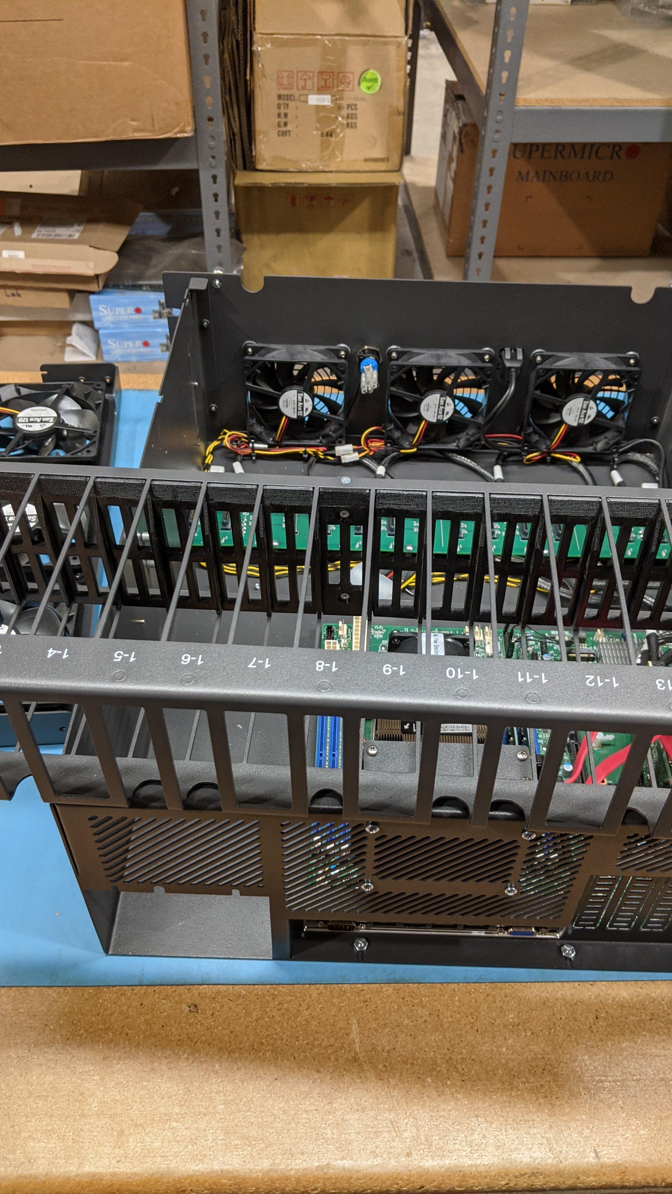
- From here, we can install the fans from the previous fan bracket on to the new fan bracket. There are two fans on this one in place of three– don’t worry about air flow, our chassis and fan configurations are made with this in mind.
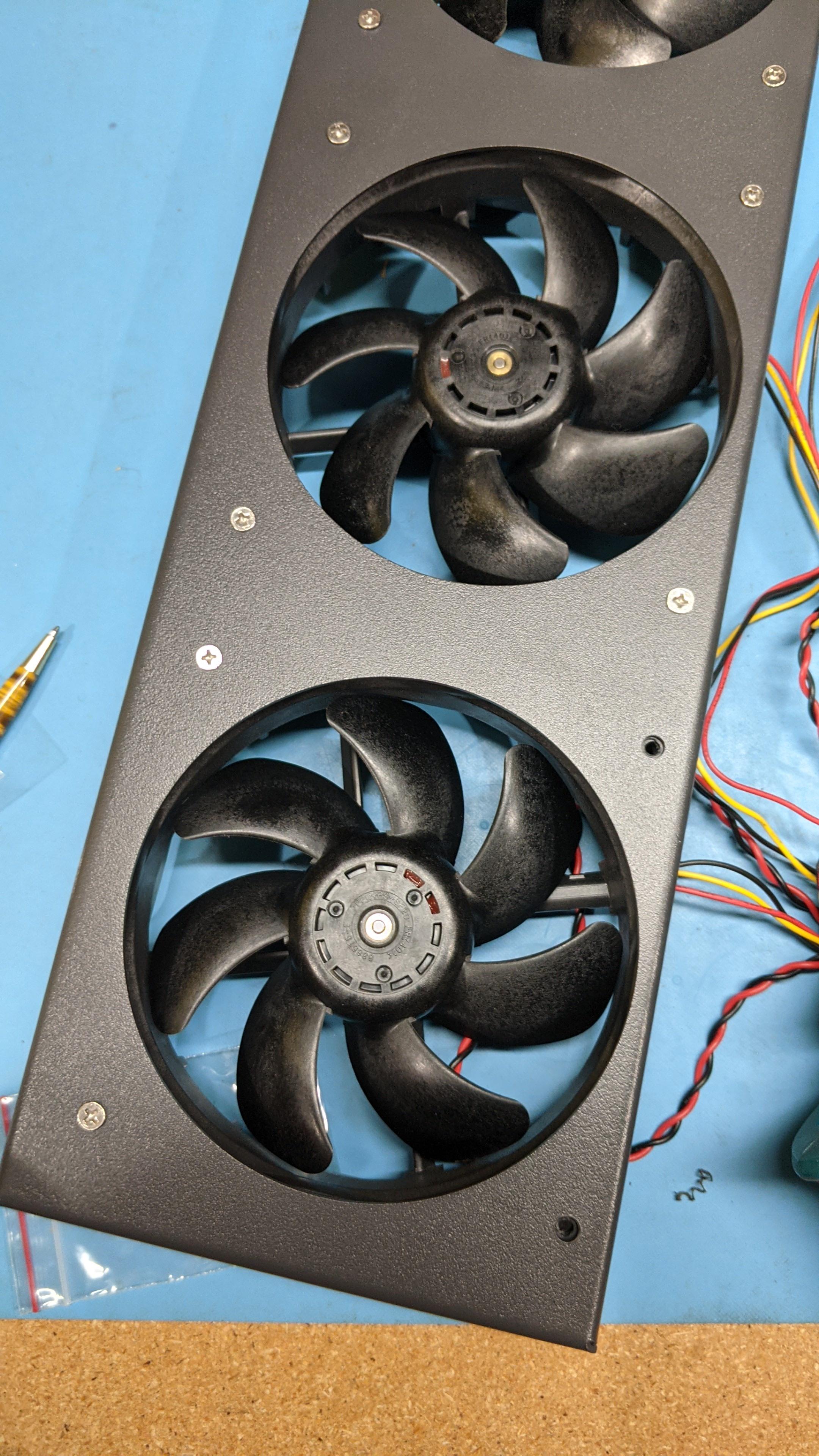
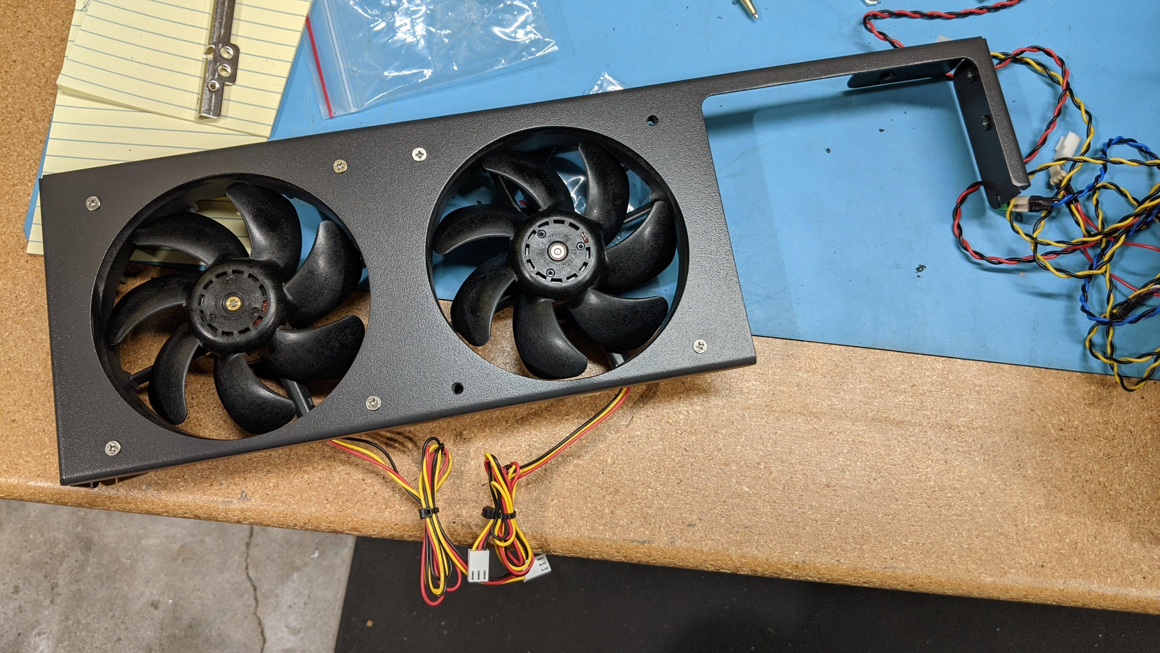
- Please be sure to face the fans the proper direction and have the header cables coming out of the bottom. The power supply should fit firmly in it’s slot– please be sure to use all the mounting screws and tighten them accordingly. Once this the PSU is installed in the chassis, the HDD bracket can be re-installed as well.
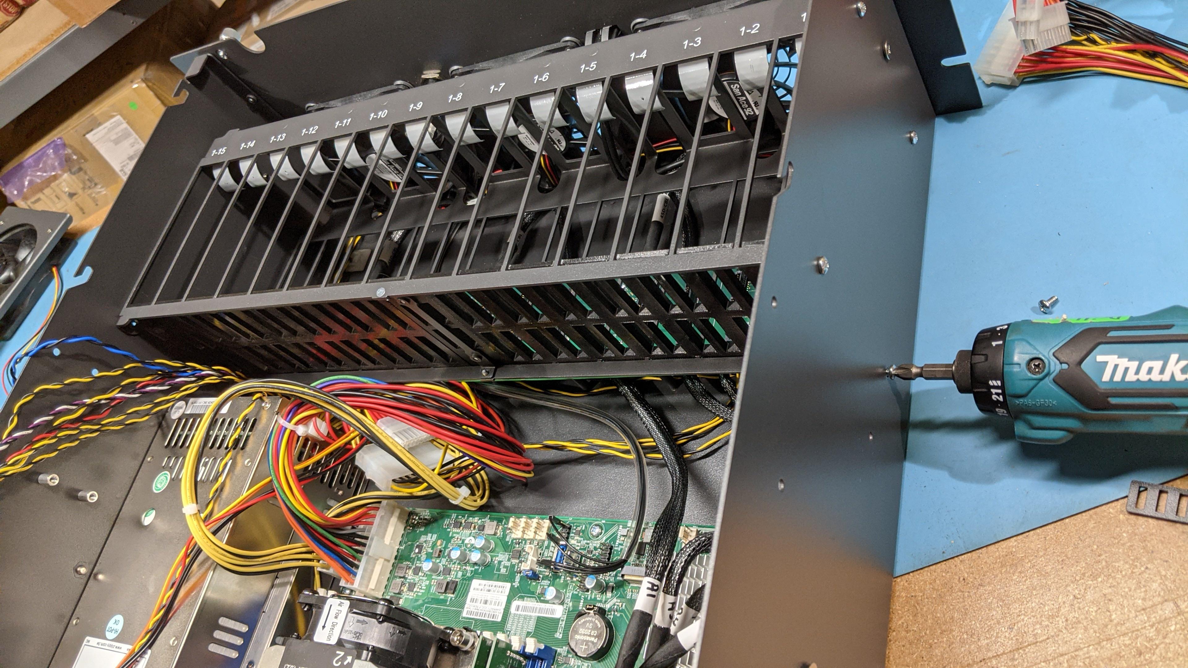
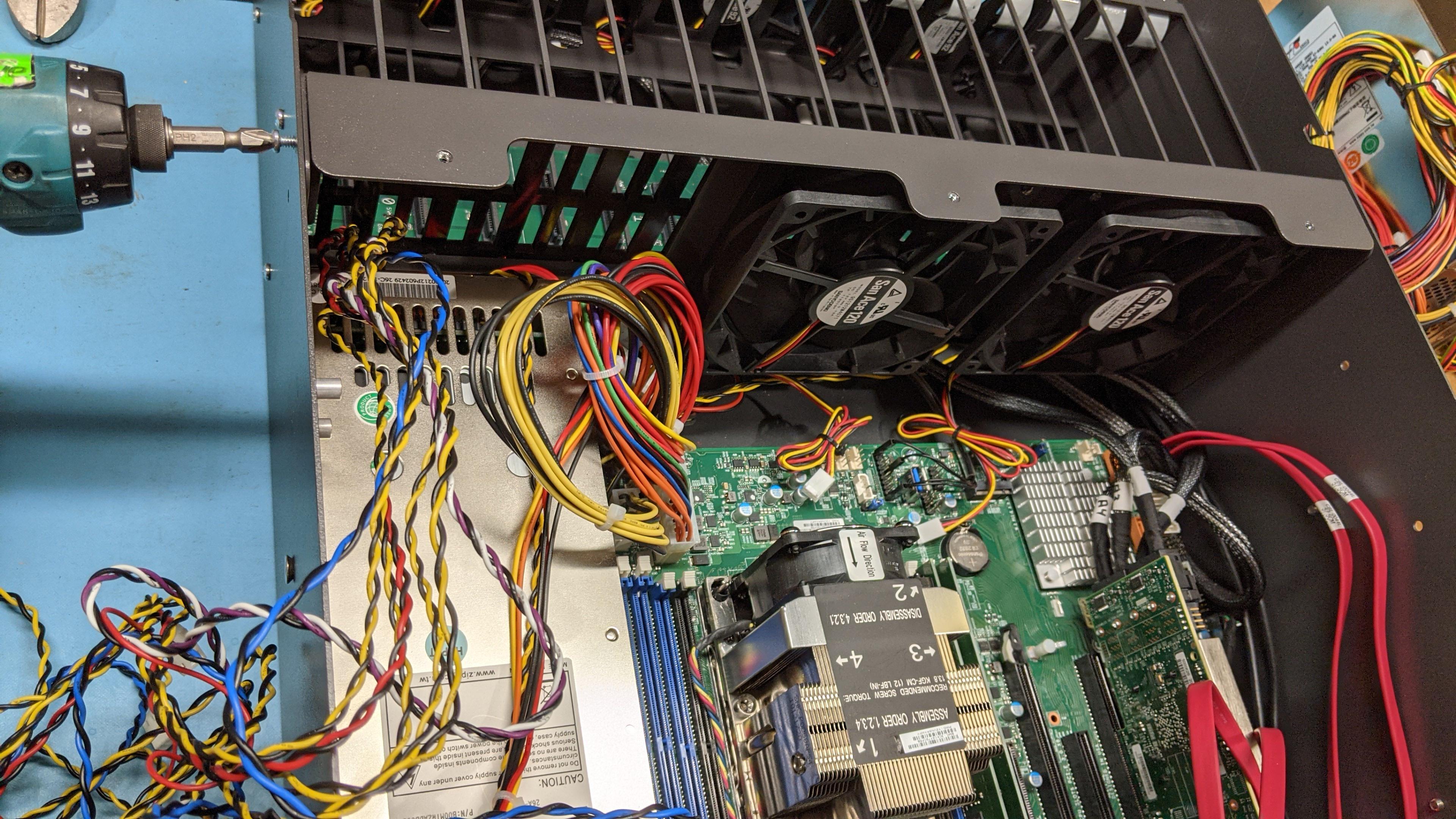
- Be sure to plug in the fan headers and the power supply connectors again. The power harness will also need to be firmly connected once more, be sure to apply some pressure to make sure it’s properly connected.
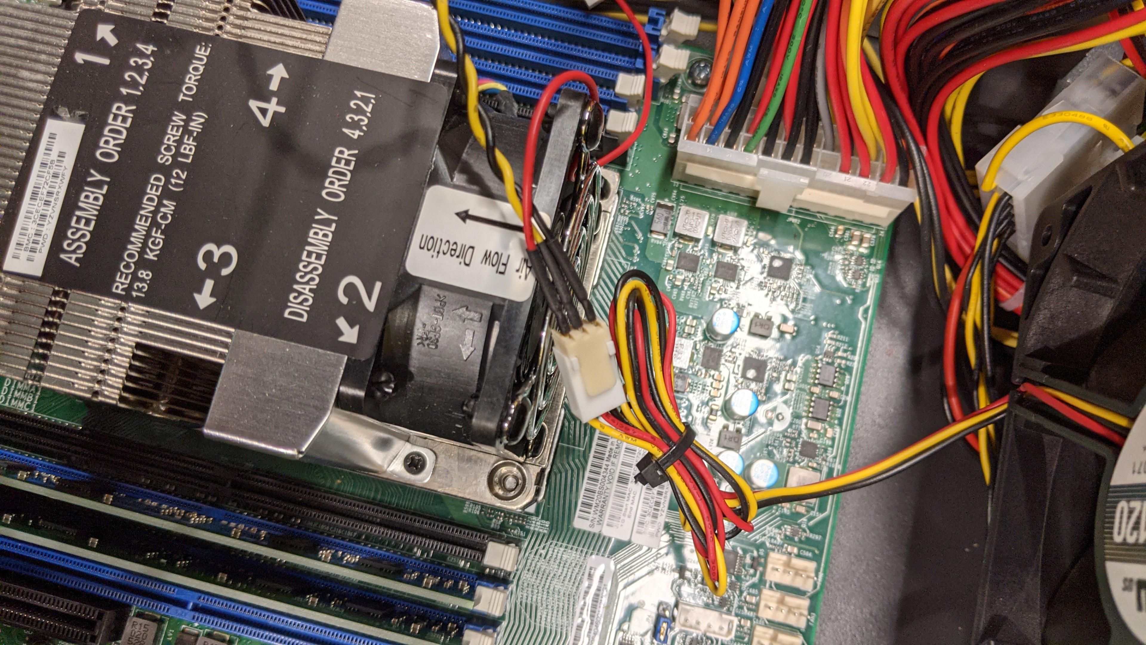
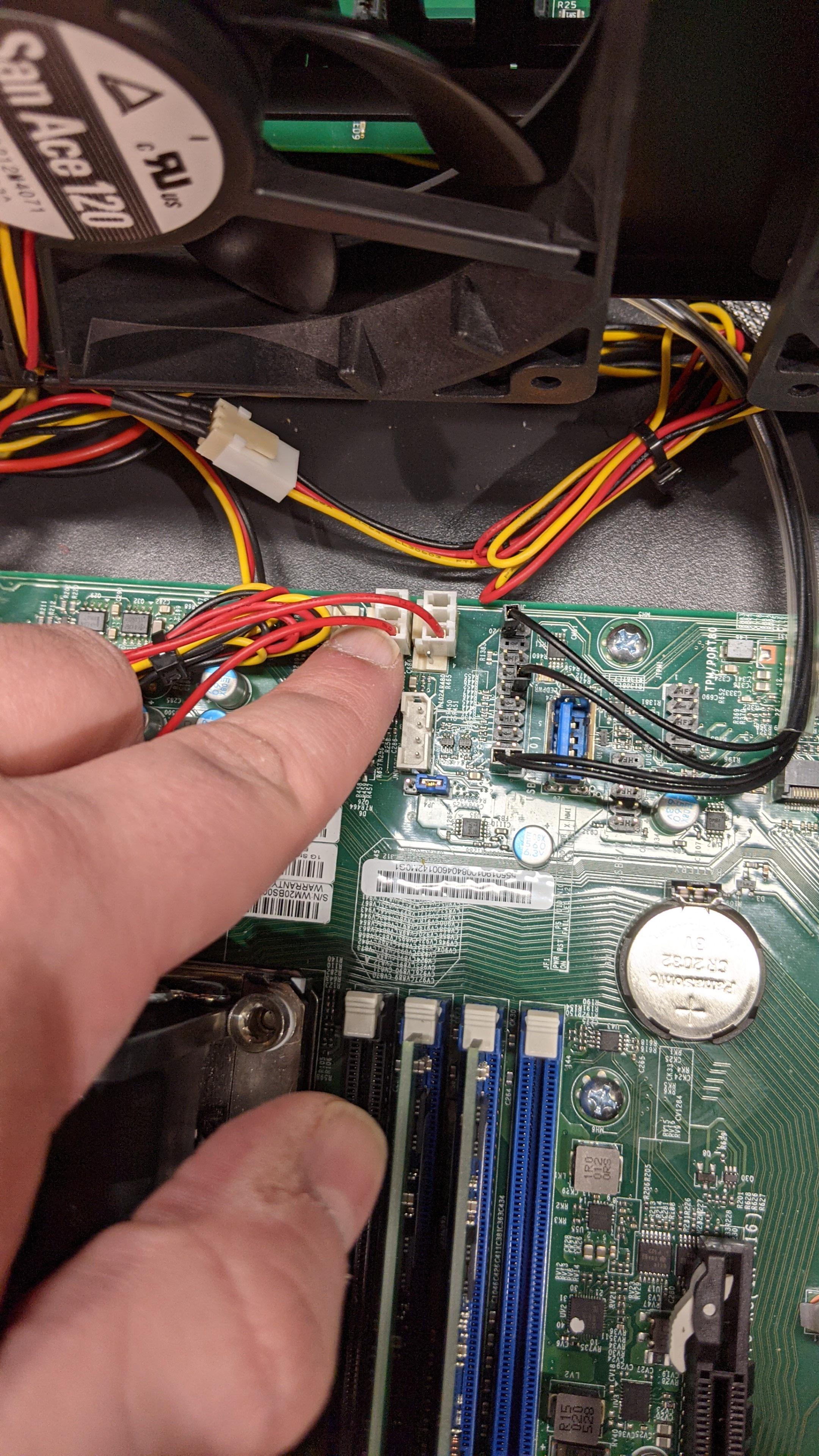
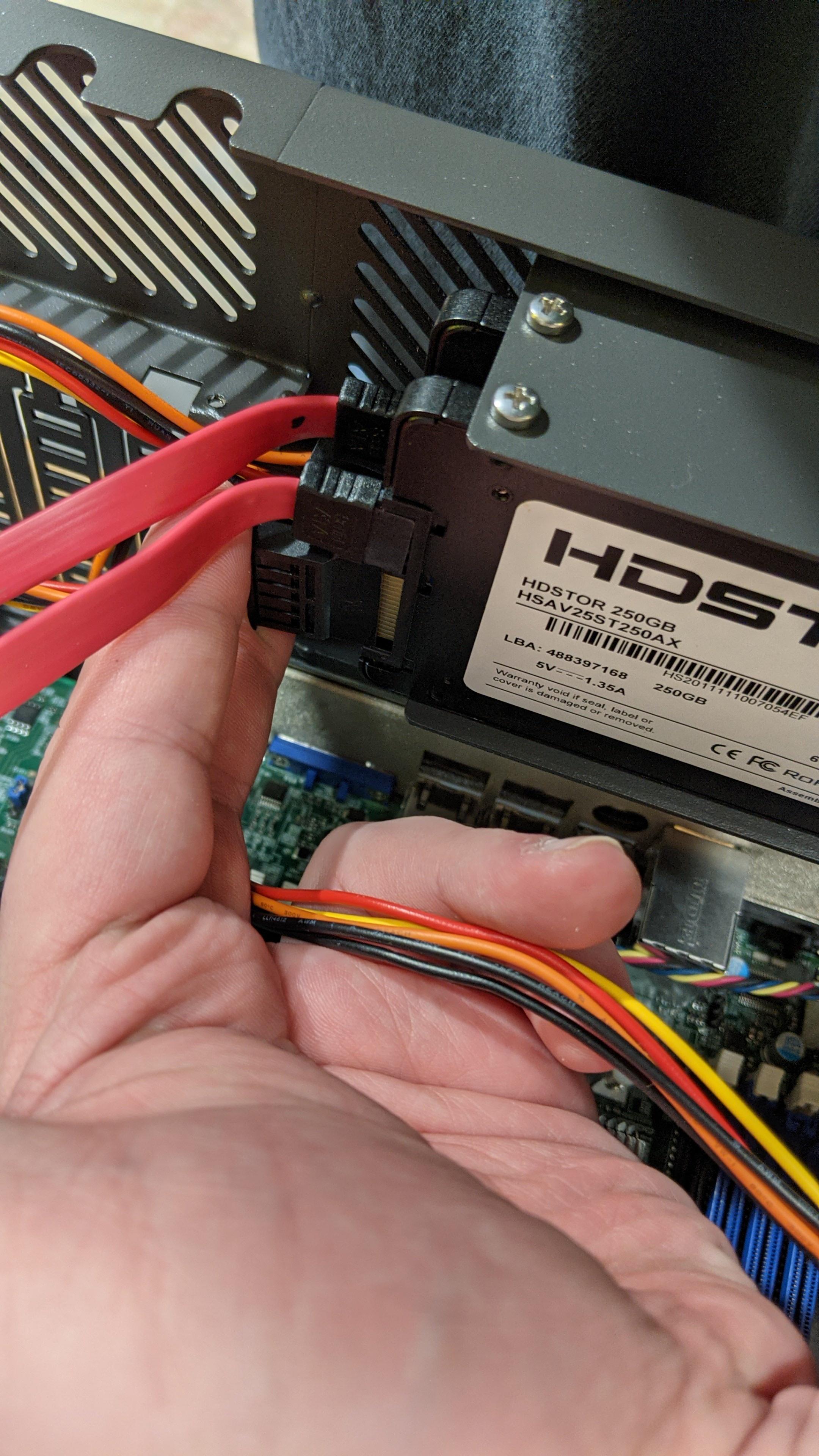
- SATA power can be returned to the boot drives now as well
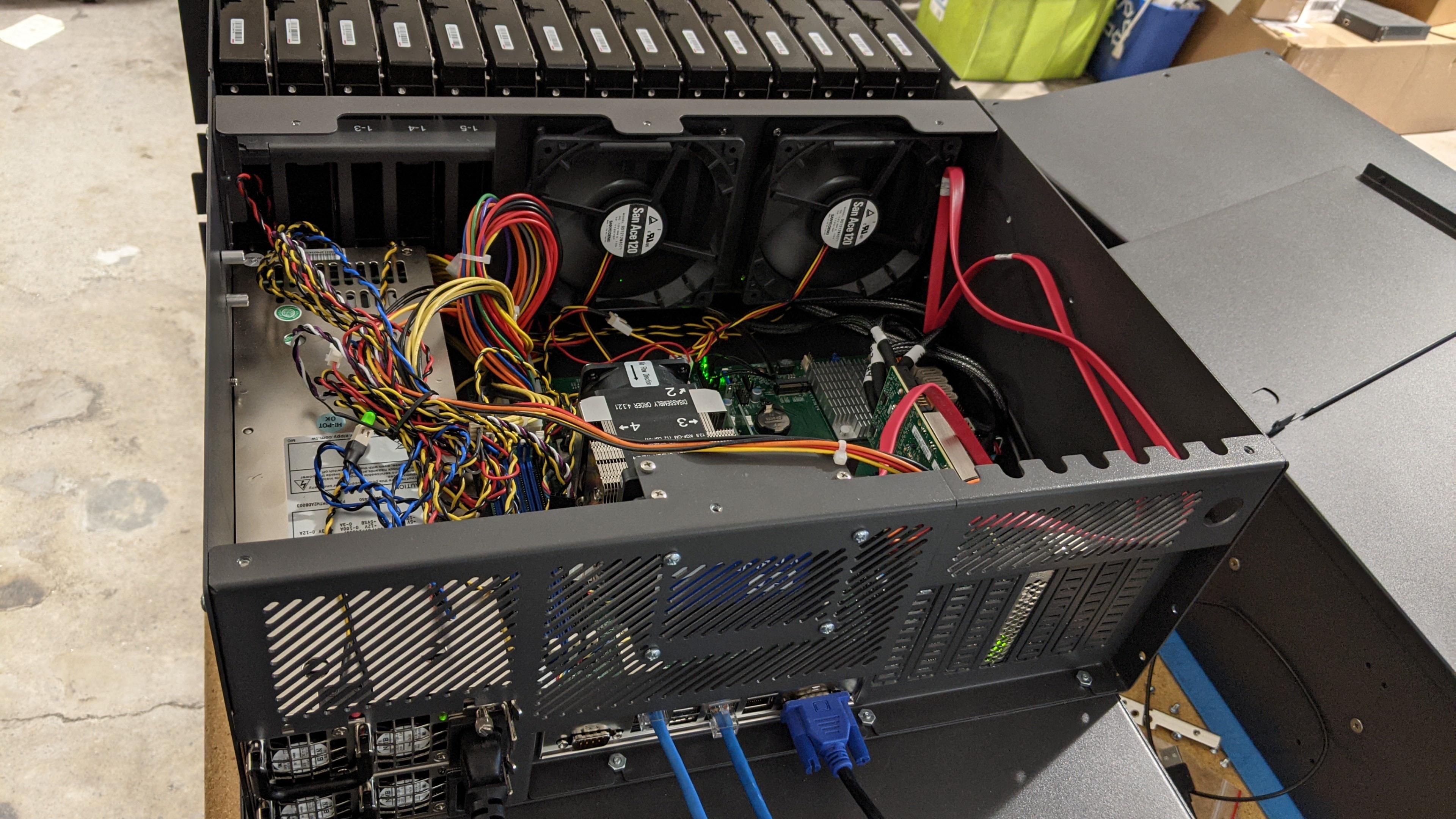
- After ensuring all the headers are connected once again, it’s time to give the unit a test boot. You may hear a beeping sound, press the red button on the power supply to silence it.

Views: 1930