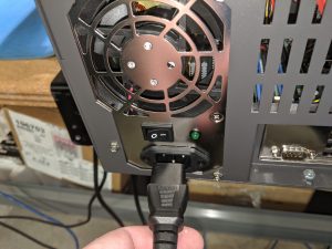
Before beginning the process of replacing a broken or defective motherboard, begin by removing all power connectors from the Storinator, and then press the power button to discharge any stored power inside of the unit. Then remove any other cables connected to the Storinator such as USB, Ethernet, VGA.
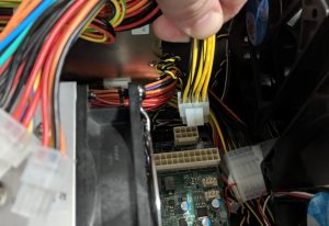
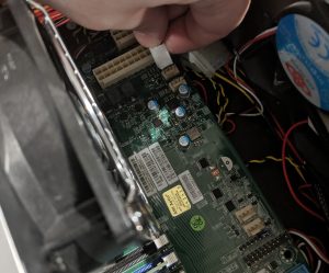
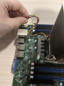
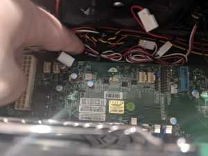
Begin by removing the CPU 8pin and the Motherboard 24pin cables from the motherboard.
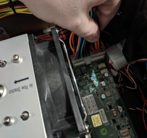
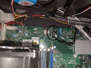
Remove the fan connectors from the fan headers. There should be 3 in total.
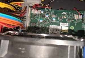
Remove the power switch and LED connectors.
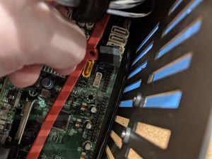
Remove 2 SATA connectors from the motherboard that are connected to the mirrored boot drives.
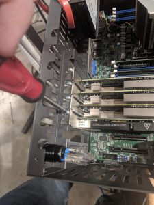
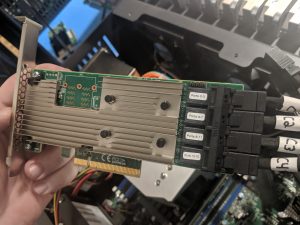
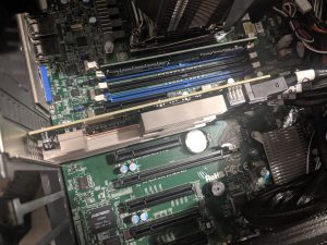
Begin removing the PCIe cards installed in the motherboard by unscrewing them. Be sure to take note of the labels on the LSI cards to know which order the cables should be reconnected in once the new motherboard is installed. Place the removed cards in a safe place.
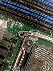
Once all PCIe cards have been removed from the motherboard, begin removing the motherboard standoff screws.
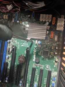
The screws can be found in the following locations:
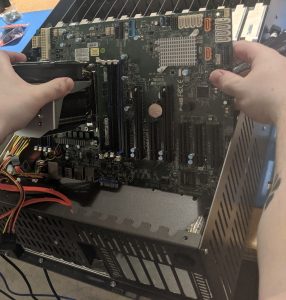
Once all screws are removed, begin removing the motherboard from the chassis. Do this by holding on to the heat-sink, and pulling it out on an angle. Try to push the SAS cables out of the way while angling the motherboard up and out.
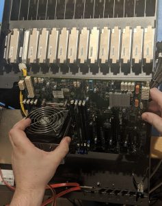
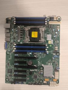
Once the faulty motherboard has been removed, bring it to a table with enough space to work on to remove the heat-sink, RAM and CPU and to put them in the new motherboard.
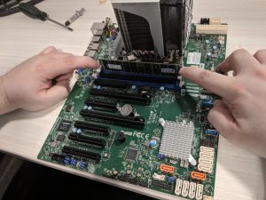
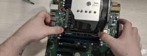
Begin by removing the RAM. Do this by pressing down on the white tabs on each end of the ram slots until the RAM stick pops up. Place the RAM DIMMS in a safe place.
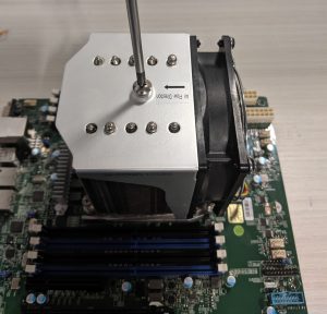
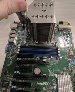
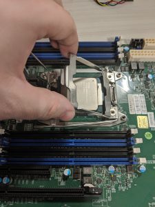
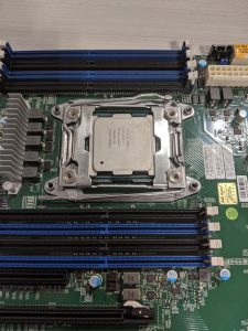
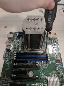
Once each RAM DIMM is removed, remove the CPU cooler. Begin by removing the screw from the top of the heat-sink.
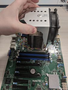
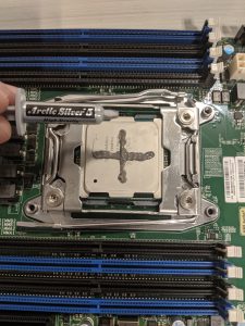
Next, pull up on the silver cover of the heat-sink until it comes off completely. Place this somewhere safe for now.
Unscrew the heat-sink from the motherboard.
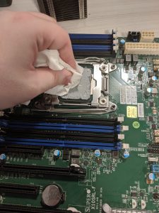
Clean the thermal paste from the CPU before removing it from the socket. Paper towel and isopropyl alcohol works best. Clean the heat-sink as well.
Once the CPU is cleaned, remove the CPU from its socket by pushing down on the first lever and unhooking it from the retaining clip, then repeat the step for the second lever.
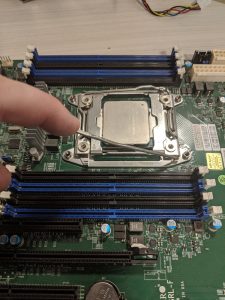
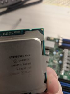
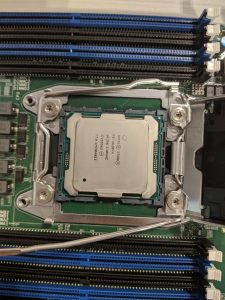
Once both levers are free, lift on the socket retainer to expose the CPU, and then remove the CPU from its socket. Try not to touch the underside of the CPU with bare hands.
Remove the new motherboard from its box and begin by repeating the previous steps to open the CPU socket.
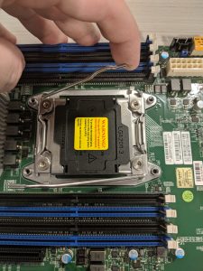
Once the socket is exposed, get ready to drop in the CPU to the new motherboard socket. To ensure proper CPU placement, line up the small gold triangle on the CPU with the triangle on the motherboard socket.
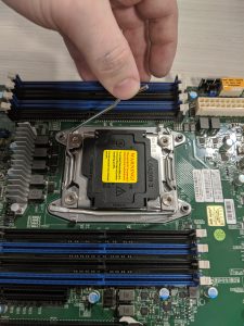
Lower the hinged socket retainer on top of the CPU, and then begin lowering the socket retainer lever shown in the image below first and then secure it under the lever retaining clip. Repeat this step with the second retainer lever.
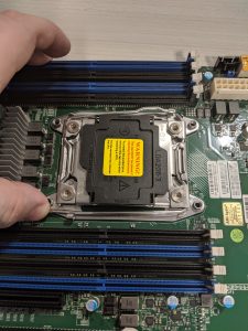
Once both levers are secured under the retaining clips, the socket protector will pop off on its own, or with little effort by hand.
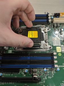
The CPU is now installed.
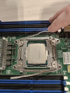
If you are reusing the same heat-sink, you will need to apply new thermal paste to the CPU. A small amount like shown in the image below is all that is needed.
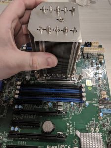
Begin lining up the heat-sink over the CPU by aligning the screws on the heat-sink with the holes on the motherboard.
Begin screwing down the heat-sink in a diagonal pattern, tightening a few turns on each screw until all screws are hand tight.
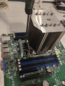
Slide the fan assembly back over the top of the heat-sink, and then tighten down the screw that goes in the center of the fan unit.
Plug the CPU fan into the correct header.
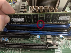
Begin inserting your RAM DIMMs back into their slots by pressing down on the white tabs on each end of the slot to open them up, and then insert the RAM into the slot ensuring the notch in the ram matches the notch in the slot. Once the RAM is in place, push down on both ends of the ram evenly until it clicks into place. RAM runs on channels. If you aren’t filling all RAM slots, be sure to insert the ram in the correct locations. Refer to the motherboard manual to know the proper placement of RAM.
The motherboard is now ready to be inserted into the chassis.
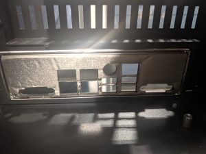
If the new motherboard has a different I/O layout, be sure to replace the I/O shield in the chassis. These will pop out quite easily from the inside by applying force from the outside.
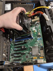
Insert the motherboard on an angle, ensuring it does not end up on top of any necessary cables.
Begin tightening the motherboard standoff screws, and then replace fan cables on motherboard fan headers. Finally, insert CPU 8 pin cable, and motherboard 24 Pin cable.
Once the motherboard is fully secured and all cables are back in place, begin re-wiring the HBA cards in the same order as noted when they were removed.
Be sure to screw down all PCIe cards.
Finally, re-wire the power button and power LED. If unsure of where to connect refer to the motherboard manual.
Your motherboard replacement is now complete, replace power to the system to begin testing.